Golf putter having spaced weight member

a golf putter and weight member technology, applied in the field of golf putters having spaced weight members, can solve the problems of less attractive appearance and heavier clubheads, and achieve the effects of improving clubhead performance, enhancing performance, and reducing weigh

Inactive Publication Date: 2005-05-31
FINN CHARLES A
View PDF12 Cites 56 Cited by
  • Summary
  • Abstract
  • Description
  • Claims
  • Application Information

AI Technical Summary

Benefits of technology

[0005]As compared with a clubhead having an identical shape and having the extra weight simply cast into the back of the clubhead, applicant's new club clearly provides enhanced performance, especially in situations where the clubhead strikes the ball off center. The length of the rearwardly extended bar, as shown, is approximately half that of the main part of the clubhead, and a significant amount of testing indicates that the clubhead can hit the ball substantially off center without causing the ball to change its direction. Actually, an even longer bar could improve the clubhead performance somewhat more, but the additional length results in a heavier clubhead and less attractive appearance.
[0006]The length of the clubface over which the ball may be hit without causing the ball to be deflected is greater than the length of the spaced bar, as shown. Typically, the clubhead may be 4-⅞″ long and the bar centered at the rear is 2-{fraction (7 / 16)}″ long. Experience with a putter made according to the invention indicates that improved performance is observed even if the point of impact with the ball is anywhere over the entire length of the striking face. Optimum performance will occur if the ball is hit within the length of the bar and a significantly improved performance is experienced even if the point of contact with the ball is outside the length of the bar.

Problems solved by technology

Actually, an even longer bar could improve the clubhead performance somewhat more, but the additional length results in a heavier clubhead and less attractive appearance.

Method used


Image

  • Golf putter having spaced weight member
  • Golf putter having spaced weight member
  • Golf putter having spaced weight member

Examples


Embodiment Construction

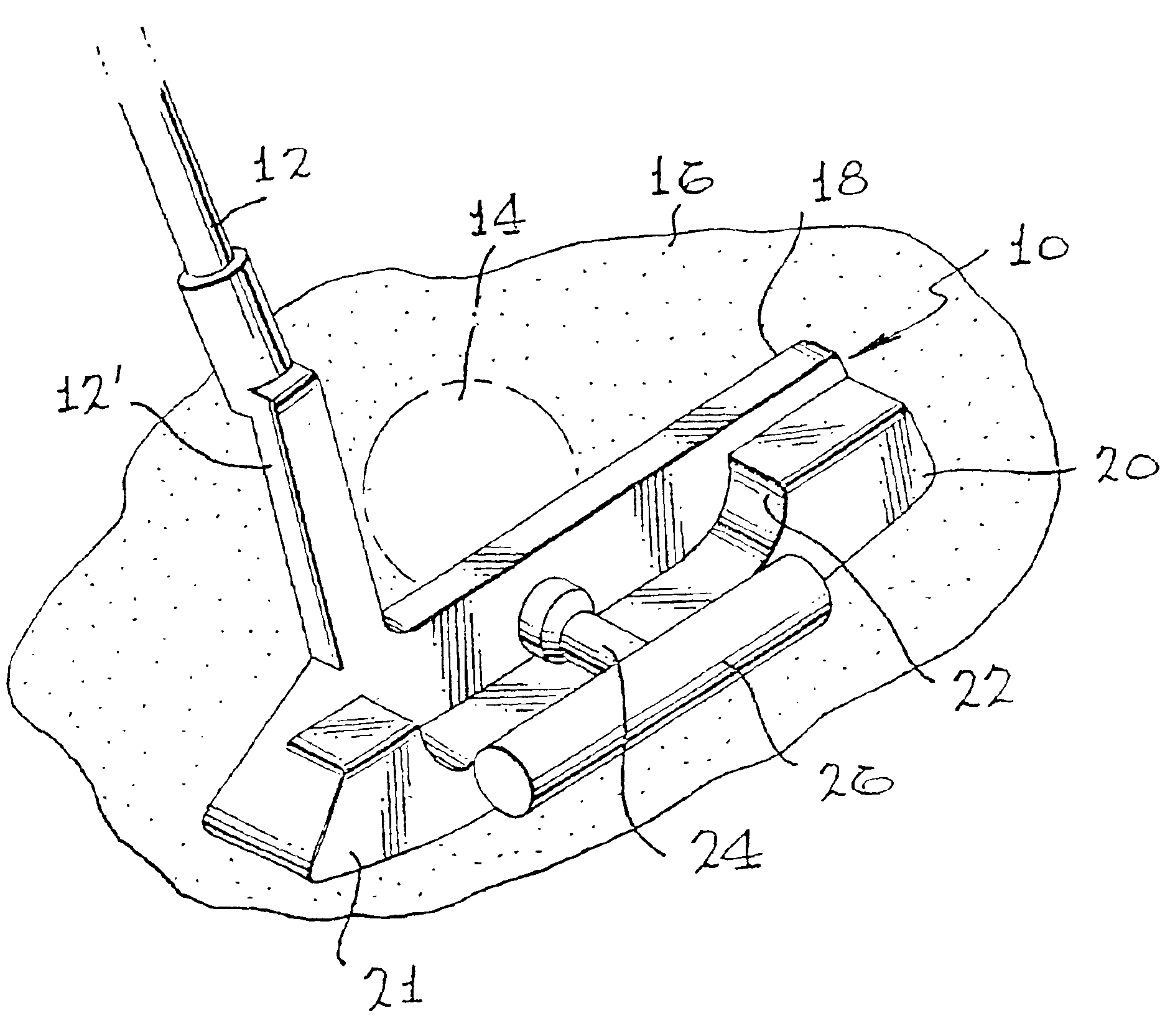
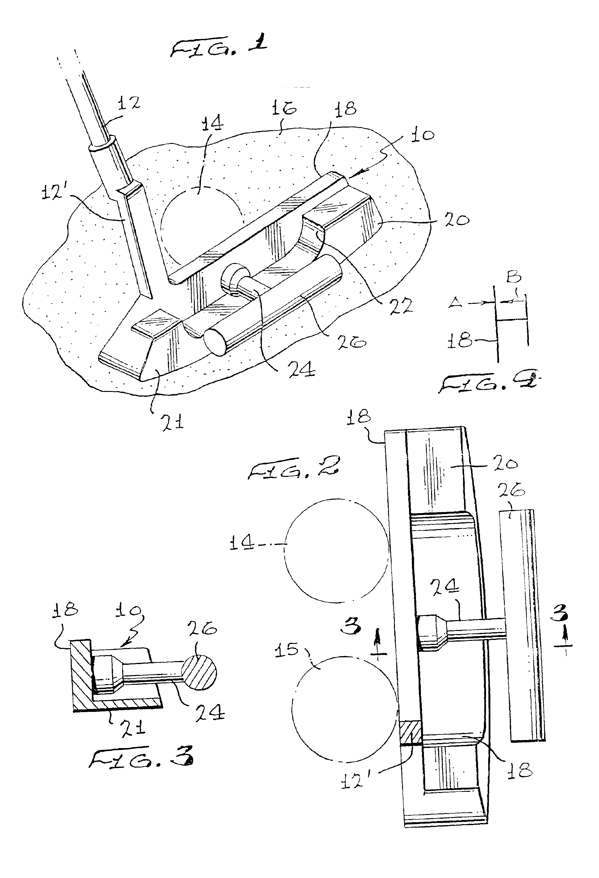
[0030]Referring now to FIG. 1, the putter clubhead 10 is secured to a shaft 12 by means of an integral hosel 12′. The hosel may also be a separate member attached to clubhead 10. The clubhead is shown addressing a bail 14, shown in phantom, on a putting green 16. The clubhead 10 includes a striking face 18 with a weighted portion 20 formed on the rear side. At the bottom of the weighted portion 20 is a soleplate 21. The weighted portion 20 extends toward the toe and heel of clubhead 10 but is cut out or relieved in the upper part of the center, as shown at numeral 22. A short rod or bar 24 is secured to, and cantilevered from, the rear side of the striking face 18 at the center of the cut out part 18, which is also essentially at the weight center of the clubhead 10. An elongated cylindrical weight 26 is secured at its exact center to bar 24 leaving the ends of weight 26 cantilevered from the point of attachment of weight 26 to bar 24.

[0031]FIG. 2 is a plan view of the clubhead 10 s...


PUM


Abstract

A golf putter is formed with a clubhead including a striking face, added weight along the bottom at the rear of the clubhead to form a soleplate and weight added to the toe and heel portions. Secured to the back side of the clubhead is a rearwardly extending support member. An elongated cylindrical weight member secured to the end of the support member is centered thereon and extends parallel to the striking face. Additional embodiments are shown wherein the elongated weight member is positioned high at the rear of the clubface, or supported on the soleplate. In one alternative embodiment the weight is concealed in a cavity within the clubhead with its support member secured to a separate striking face member. In another embodiment, the weight member is faired into an open cavity and spaced from the walls of the cavity.

Description

REFERENCE TO RELATED APPLICATION[0001]This non-provisional patent application is based upon U.S. Provisional Patent Application Ser. No. 60 / 227,741 filed Aug. 24, 2000 and hereby claims the benefit of the filing date thereof.BACKGROUND OF THE INVENTION[0002]Because of the great interest in golf and golf equipment, there is a continuing effort to devise newer and better golf clubs. This applies to putters, as well as other clubs, and a visit to any well stocked golf professional's shop will disclose a number of designs of golf putters available. Variations include clubs, particularly putters, having heads with various amounts of offset from the shaft, various shapes of head and various weighting arrangements. Great effort has been expended in attempting to distribute the weight on the clubhead so that the club will swing straight and true.[0003]Specifically, most golf putters today are weighted toward the bottom of the club with varying proportions of the weight placed toward the hee...

Claims


Application Information

Patent Timeline
Patent Type & Authority Patents(United States)
IPC IPC(8): A63B53/04A63B53/02A63B59/00
CPCA63B53/0487A63B59/0074A63B2053/021A63B2053/0416A63B2053/042A63B2053/0491A63B2053/0425A63B2053/0433A63B2053/0437A63B2053/0441A63B53/021A63B53/0416A63B53/042A63B53/0425A63B53/0433A63B53/0437A63B53/0441A63B60/42
Inventor FINN, CHARLES A.
Owner FINN CHARLES A
Why Eureka
Try Eureka