Battery pack

a battery pack and battery technology, applied in the field of batteries, can solve the problems of increasing the resistance of the assembled battery, the inability of the structure to exert the vibration isolation effect of preventing vibration, and the vibration inputted to the case is undetected to the assembled battery and the individual unit cells, so as to prevent the vibration of the assembled battery

Active Publication Date: 2005-05-31
ENVISION AESC JAPAN LTD
View PDF12 Cites 64 Cited by
  • Summary
  • Abstract
  • Description
  • Claims
  • Application Information

AI Technical Summary

Benefits of technology

[0007]However, the conventional structures are structures incapable of exerting a vibration isolation effect of preventing vibrations of the assembled battery. Therefore, if the battery pack is used under an environment where the vibrations are inputted to the case, then the vibrations inputted to the case are undesirably transmitted to the entire assembled battery and the individual unit cells. Accordingly, there is a possibility that terminal portions and bus bars, which are connection portions among the cells, will fatigue owing to the transmitted vibrations, resulting in its resistance increase and its fatigue breakage.

Problems solved by technology

However, the conventional structures are structures incapable of exerting a vibration isolation effect of preventing vibrations of the assembled battery.
Therefore, if the battery pack is used under an environment where the vibrations are inputted to the case, then the vibrations inputted to the case are undesirably transmitted to the entire assembled battery and the individual unit cells.
Accordingly, there is a possibility that terminal portions and bus bars, which are connection portions among the cells, will fatigue owing to the transmitted vibrations, resulting in its resistance increase and its fatigue breakage.

Method used


Image

  • Battery pack
  • Battery pack
  • Battery pack

Examples


example 1

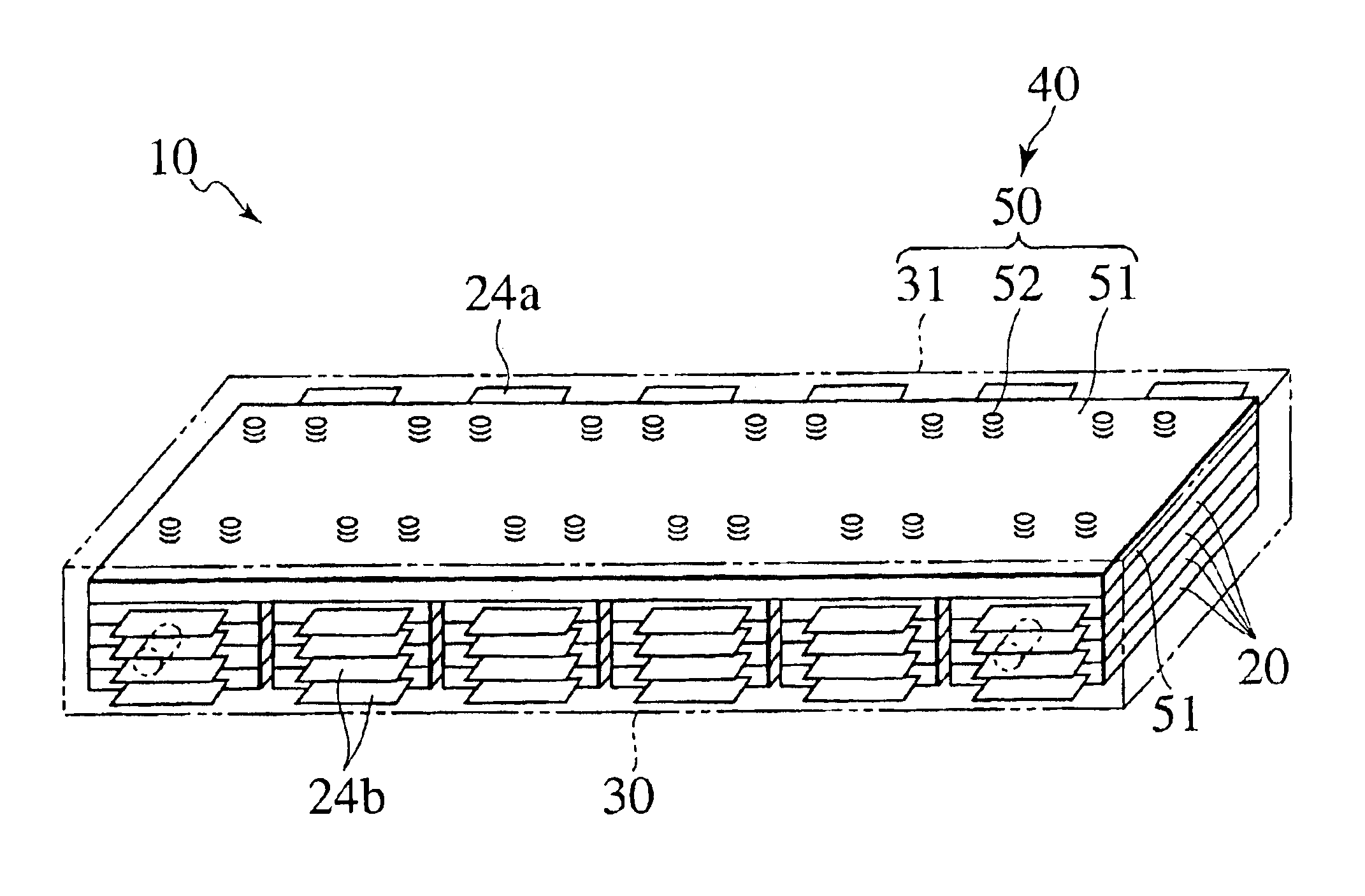
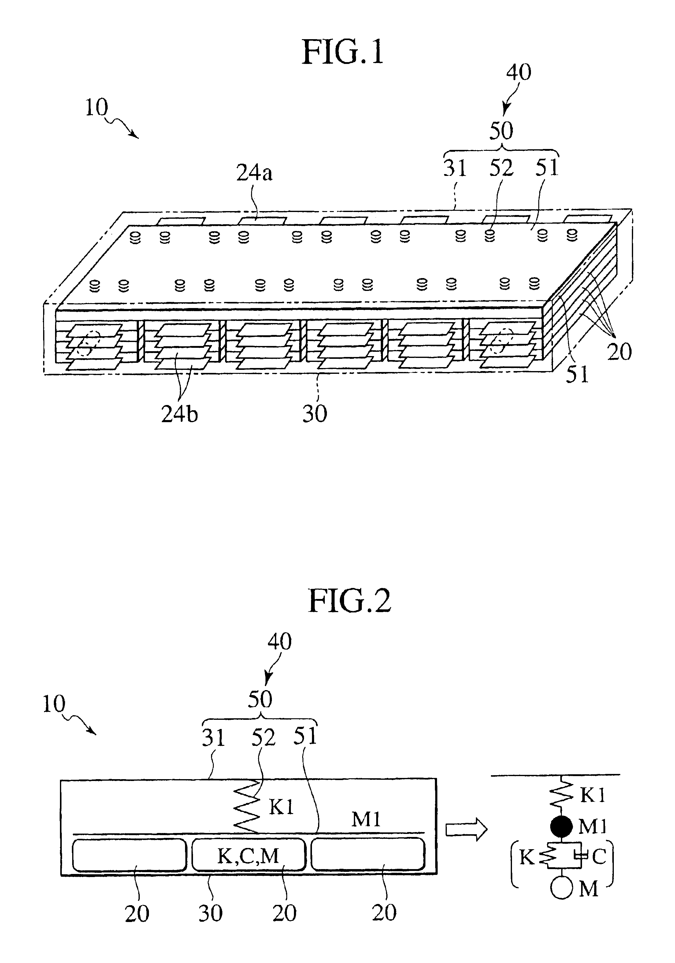
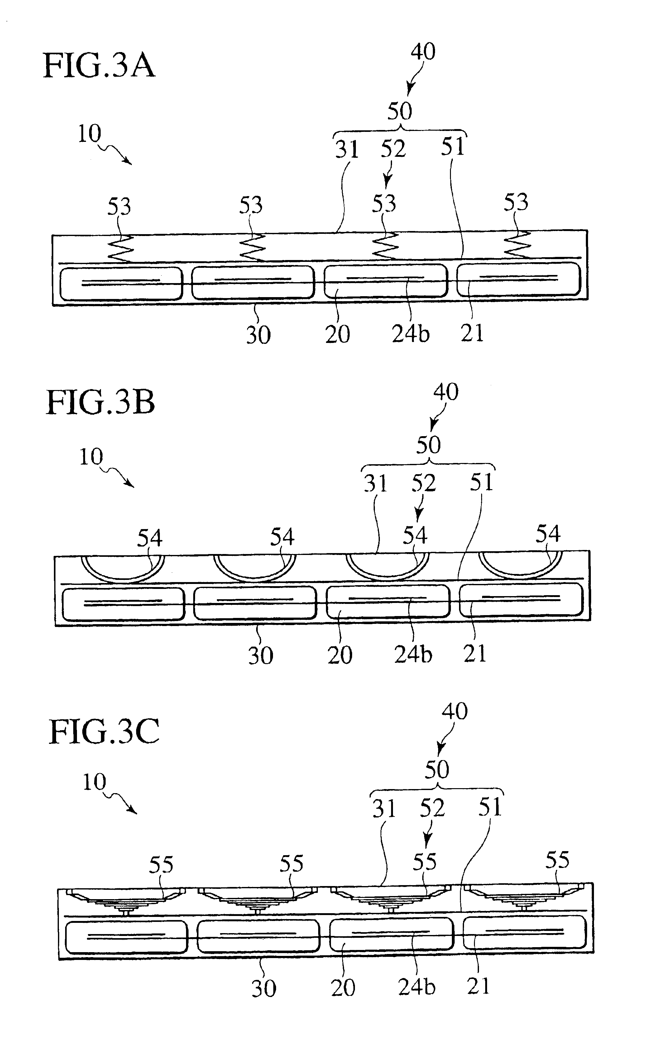
[0104]Four pieces of the laminated package unit cells 20 in the form shown in FIGS. 11A and 11B were used. The thickness of each unit cell 20 is 5 mm, and the width of the lab terminals 24a and 24b is 50% of that of the cell body 23. The unit cells 20 were connected to one another in four-parallel, and thus the battery pack 10 shown in FIG. 3A was manufactured. Specifically, four pieces of the unit cells 20 were connected in parallel to be installed as an assembled battery in the metal-made outer case 30. A metal plate as the press plate 51 was installed on the upper portions of the unit cells 20. The metal plate is an aluminum plate having a thickness of 1 mm. Then, the press structure 50 that pressed the metal plate with a surface pressure of 1 kgf / cm2 was formed in such a manner that each of the four coil springs 53 pressed the approximately center portion of the unit cell 20.

[0105]For the battery pack of Example 1, the spectrum of free oscillation of the outer case 30 was measur...

example 2

[0106]The elastic members 52 of the press structure 50 were changed from the coil springs 53 to the disk springs 54, and the battery pack 10 shown in FIG. 3B was manufactured. As shown in Tables 1 and 2, Example 2 is different from Example 1 also in the cell's Young's modulus, the ratio of the pressing force and the cell's Young's modulus, the ratio of the pressed area and the electrode projection area of the unit cell, the ratio of the tab width and the cell width, and the unit cell thickness.

[0107]The primary resonance frequency difference of the battery pack 10 of Example 2 was about. 10 Hz, and the average reduction amount was 2 dB.

example 3

[0108]The elastic members 52 of the press structure 50 were changed from the coil springs 53 to the laminated leaf springs 55, and the battery pack 10 shown in FIG. 3C was manufactured. As shown in Tables 1 and 2, Example 3 is different from Example 1 also in the pressing force, the cell's Young's modulus, the ratio of the pressing force and the cell's Young's modulus, the ratio of the tab width and the cell width, and the unit cell thickness.

[0109]The primary resonance frequency difference of the battery pack 10 of Example 3 was about 100 Hz, and the average reduction amount was 2 dB.


PUM

PropertyMeasurementUnit
thicknessaaaaaaaaaa
resonance frequencyaaaaaaaaaa

Abstract

A battery pack has a unit cell packaged by a package material of a laminate type, an outer case which accommodates the unit cell therein, and a vibration isolation device which attenuates vibrations inputted to the outer case and transmitted to the unit cell by pressing one side surface of the unit cell. The vibration isolation device is disposed between the unit cell and the outer case, and includes a first press structure which presses the one side surface of the unit cell. The first press structure is constituted by connecting one surface of the outer case, the one surface facing to the one side surface of the unit cell, and a press plate abutting against the one side surface of the unit cell with an elastic member interposed therebetween.

Description

BACKGROUND OF THE INVENTION[0001]1. Field of the Invention[0002]The present invention relates to a battery pack accommodating a battery packaged by a package material in a case, and more specifically, to a battery pack preventing a performance deterioration of unit cells and achieving reduction of vibrations inputted thereto from the outside.[0003]2. Description of the Related Art[0004]A battery pack for an assembled battery includes an assembled battery and a case for accommodating the assembled battery therein. The assembled battery is constituted by electrically connecting a plurality of unit cells to one another.[0005]As a conventional structure of pressing an assembled battery, a structure has been known, in which an assembled battery is sandwiched between a pair of restriction plates, and the pair of restriction plates are mutually coupled with coupling rods interposed therebetween (refer to Japanese Patent Application Laid-Open No. 2001-236937). Moreover, another structure ha...

Claims


Application Information

Patent Timeline
Patent Type & Authority Patents(United States)
IPC IPC(8): B60R16/04H01M2/04H01M2/10H01M2/00H01M2/02H01M6/46H01M6/42H01M10/42H01M50/119H01M50/133H01M50/211H01M50/224H01M50/242H01M50/249H01M50/289
CPCH01M2/0262H01M2/0287H01M2/1077H01M10/42B60L11/1875B60L11/1879B60L11/1864H01M2/0275Y02T10/7061B60L2270/145Y02T10/7005B60L58/21B60L58/27B60L50/64Y02T10/70Y02E60/10H01M50/124H01M50/249H01M50/224H01M50/133H01M50/242H01M50/211H01M50/289H01M50/119
Inventor WATANABE, KYOUICHIHORIE, HIDEAKI
Owner ENVISION AESC JAPAN LTD
Why Eureka
Try Eureka