Fixing apparatus

Inactive Publication Date: 2005-05-31
KK TOSHIBA +1
View PDF21 Cites 55 Cited by
  • Summary
  • Abstract
  • Description
  • Claims
  • Application Information

AI Technical Summary

Benefits of technology

[0014]It is an object of an aspect of the present invention to suppress changes in the intensity of a current flowing through a circuit, i.e., voltage fluctuations in a heating apparatus u

Problems solved by technology

This has a problem of an increase in a cross section of an electric wire used in the induction coil.
Furthermore, since a size of the induction coil is increased owing to a fact that an electric wire with a large cross section must be used, an outside diameter of the heat roller is disadvantageously increased when the induction coil is arranged inside the heat roller in order to increase the utilization efficiency of a magnetic flux generated from the induction coil.
It is t

Method used


Image

  • Fixing apparatus
  • Fixing apparatus
  • Fixing apparatus

Examples


Embodiment Construction

[0049]Preferred embodiments according to the present invention will now be described in detail hereinafter with reference to the accompanying drawings.

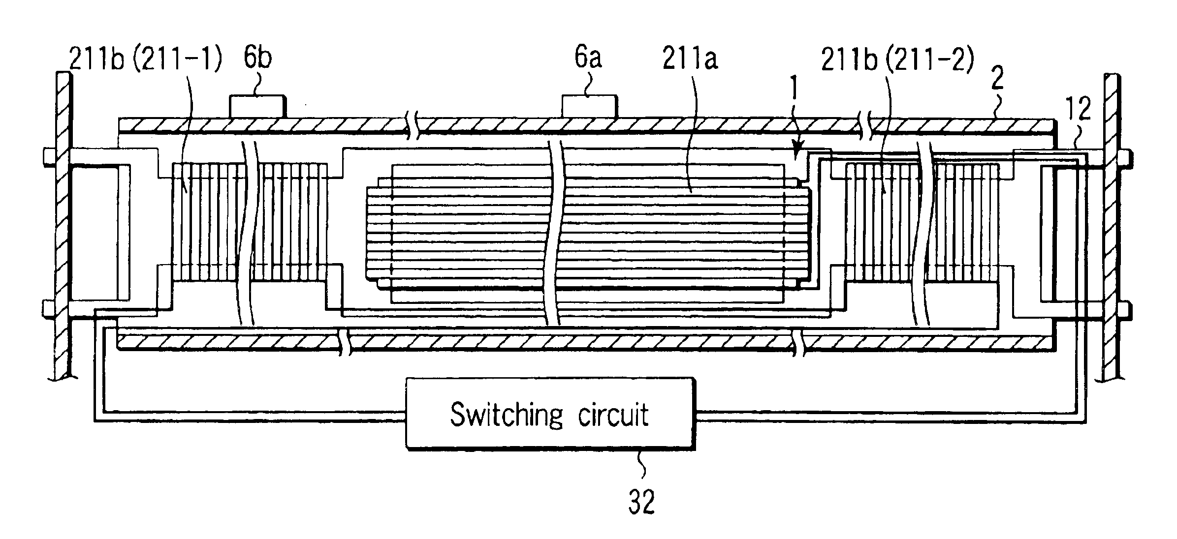
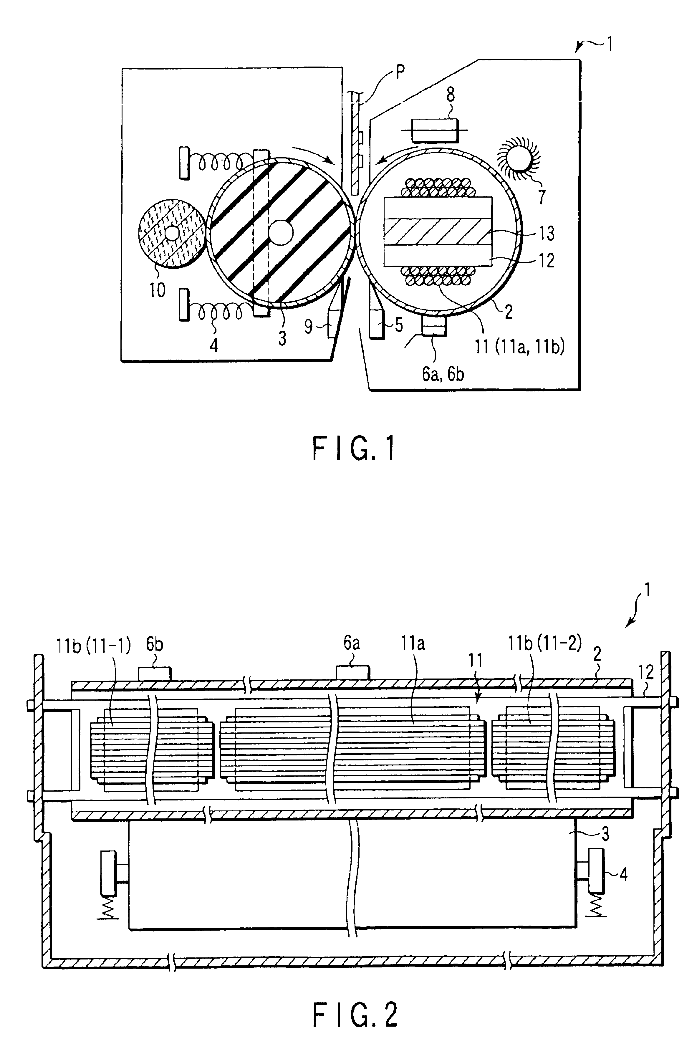
[0050]FIG. 1 is a schematic cross-sectional view showing a state that a fixing apparatus 1 to which the embodiment according to the present invention is applied is cut at the substantial center in the longitudinal direction, and FIG. 2 is a schematic plane view showing a state that the fixing apparatus 1 is seen from the plane direction with a non-illustrated cover and the like of the fixing apparatus shown in FIG. 1 being removed.

[0051]The fixing apparatus 1 includes a fixing (heat) roller 2 having a diameter of approximately 20 mm and a press (pressure) roller 3 having a diameter of approximately 20 mm.

[0052]The heat roller 2 is a hollow cylindrical body formed of a metal having a thickness of approximately 1 mm, or more preferably approximately 0.5 mm. It is to be noted that the roller 2 is formed of iron in this embodiment but it ...


PUM


Abstract

A fixing apparatus an aspect of the present invention includes, a heating object which generates the heat by a magnetic flux produced from a coil which generates a predetermined magnetic flux by electromagnetic induction in accordance with a frequency of an input current, and a pressurization mechanism which can provide a predetermined pressure to the heating object, and a coil of the heating object is formed of a litz wire obtained by twisting the number of conductors having a small cross section which are not affected by the skin effect caused due to the frequency of the input current, the number of which allows passage of a quantity of current to be inputted.

Description

CROSS-REFERENCE TO RELATED APPLICATIONS[0001]This application is based upon and claims the benefit of priority from the prior Japanese Patent Application No. 2002-166050, filed Jun. 6, 2002, the entire contents of which are incorporated herein by reference.BACKGROUND OF THE INVENTION[0002]1. Field of the Invention[0003]The present invention relates to a heating apparatus utilizing induction heating, and more particularly to a fixing apparatus which fixes a toner which can be utilized in an electrophotographic type copying apparatus or a printer apparatus using a toner having the thermofusion property as a visualization agent.[0004]2. Description of the Related Art[0005]A fixing apparatus incorporated in a copying apparatus using an electrophotographic process heats and melts a toner formed on a transfer medium, and fixes the toner on the transfer medium.[0006]As a method of heating the toner which can be utilized in the fixing apparatus, a method of using the heat radiated from a fi...

Claims


Application Information

Patent Timeline
IPC IPC(8): B41J2/01G03G15/20H05B6/44H05B6/14H05B6/36
CPCG03G15/2064G03G15/2053
Inventor TAKAGI, OSAMUKINOUCHI, SATOSHI
Owner KK TOSHIBA
Why Eureka
Try Eureka