Imaging apparatus

a technology of imaging apparatus and chamber, which is applied in the field of imaging systems, can solve the problems of diverse lighting needs during image capture, present particular challenges to design, and may not be suitable for many imaging applications, and achieve the effects of improving door seal arrangement, improving illumination control, and improving door closing mechanisms

Inactive Publication Date: 2005-05-31
XENOGEN CORP
View PDF9 Cites 15 Cited by
  • Summary
  • Abstract
  • Description
  • Claims
  • Application Information

AI Technical Summary

Benefits of technology

[0007]The present invention relates to an improved imaging apparatus that allow a user to perform numerous imaging operations. The present invention may include one or more improvements to imaging box design to improve illumination control within the imaging box, such as improved door seal arrangements, improved door closing mechanisms, and improved light seals between housing surfaces. The present invention may also include one or more improvements to imaging apparatus design to facilitate image capture, such as: an automated filter select device, automated focus control, f-stop adjustment and stage height, and improved internal illumination for capturing photographic images.
[0008]In one aspect, the present invention provides a box or chamber device that is substantially more “light-tight” than conventional light boxes, and thereby allows for more sensitive and accurate detection and imaging of low intensity light sources. The present invention also provides a variety of new features and improvements to the light box and accompanying imaging components to make the imaging process more convenient and accurate than was possible with “prior art” light boxes.

Problems solved by technology

Such imaging applications present particular challenges to the design of a box or chamber in which the sample is contained during imaging.
One particular challenge to imaging box design is the diverse lighting needs required during image capture.
Thus, conventional imaging boxes or specimen chambers may not be adequate for many imaging applications, e.g., when the imaging involves the capture of low intensity light on the order of individual photons.

Method used


Image

  • Imaging apparatus
  • Imaging apparatus
  • Imaging apparatus

Examples


Embodiment Construction

[0043]In the following detailed description of the present invention, numerous specific embodiments are set forth in order to provide a thorough understanding of the invention. However, as will be apparent to those skilled in the art, the present invention may be practiced without these specific details or by using alternate elements or processes. In other instances well known processes, components, and designs have not been described in detail so as not to unnecessarily obscure aspects of the present invention.

I. Imaging System

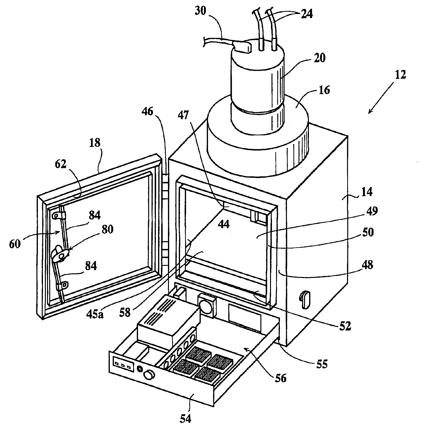
[0044]In one aspect, the present invention relates generally to improved imaging systems. FIG. 2 illustrates an imaging system 10 configured to capture photographic and luminescence images in accordance with one embodiment of the present invention. The imaging system 10 may be used for imaging a low intensity light source, such as luminescence from luciferase-expressing cells, fluorescence from fluorescing molecules, and the like. The low intensity light sour...


PUM

PropertyMeasurementUnit
compressibleaaaaaaaaaa
securing forceaaaaaaaaaa
temperatureaaaaaaaaaa

Abstract

An improved imaging apparatus is disclosed that allows a user to perform numerous imaging operations. The imaging apparatus may include one or more improvements to imaging box design to improve illumination control within the imaging box, such as improved door seal arrangements, improved door closing mechanisms, and improved light seals. The present invention may also include one or more improvements to imaging apparatus design to facilitate image capture, such as: an automated filter select device, a moveable stage, automated focus control, f-stop adjustment and stage height, and improved internal illumination for capturing photographic images.

Description

CROSS-REFERENCE TO RELATED APPLICATION[0001]This application is a divisional of prior application Ser. No. 09 / 795,056 filed Feb. 21, 2001, now U.S. Pat. No. 6,775,567, which claims priority under 35 U.S.C. §119(e) of Provisional Patent Application No. 60 / 184,859, filed on Feb. 25, 2000.FIELD OF THE INVENTION[0002]The present invention relates generally to imaging systems. More specifically, the present invention relates to an imaging box which forms part of an imaging system used for imaging low intensity light sources, and also relates to numerous improvements to various components of an imaging box.BACKGROUND OF THE INVENTION[0003]One specialized type of imaging involves the capture of low intensity light—on the order of individual photons—from a light emitting sample. The source of the light indicates portions of the sample where an activity of interest may be taking place. For example, specialized in-vivo imaging applications may include analysis of one or more representations o...

Claims


Application Information

Patent Timeline
Patent Type & Authority Patents(United States)
IPC IPC(8): G01N21/01G01N21/64A47B85/00G01N21/76H04N5/222H04N5/225H04N7/18
CPCG01N21/01G02B27/0018G02B21/16
Inventor CABLE, MICHAEL D.NELSON, MICHAEL BORICE, BRADLEY W.RASCO, CHRISTOPHER A.SPRAGUE, DAVID NNILSON, DAVID G.DALGETTY, RICK
Owner XENOGEN CORP
Why Eureka
Try Eureka