Method of and apparatus for communicating data structures between devices in a networking environment

a network environment and data structure technology, applied in the field of networked device communication, can solve the problem of no method for allowing control devices in the network to monitor schedule data

Inactive Publication Date: 2005-05-31
SONY CORP +1
View PDF43 Cites 38 Cited by
  • Summary
  • Abstract
  • Description
  • Claims
  • Application Information

AI Technical Summary

Benefits of technology

[0010]The method of and apparatus for communicating data structures between devices in a networking environment of the present invention is an architecture, a method and a system for monitoring data structures written to and stored in a descriptor mechanism. The invention is particularly useful for monitoring data structures submitted to a bulletin board subunit from networked control devices. Preferably, the control devices are networked together with an IEEE 1395-1995 serial bus network and the bulletin board subunit is an AV / C resource bulletin board subunit that is dedicated to a resource device, such as a VCR or other audio video device. The data structures are preferably resource schedule entries, or portions thereof, posted to acquire resource time from a resource subunit of the resource device.
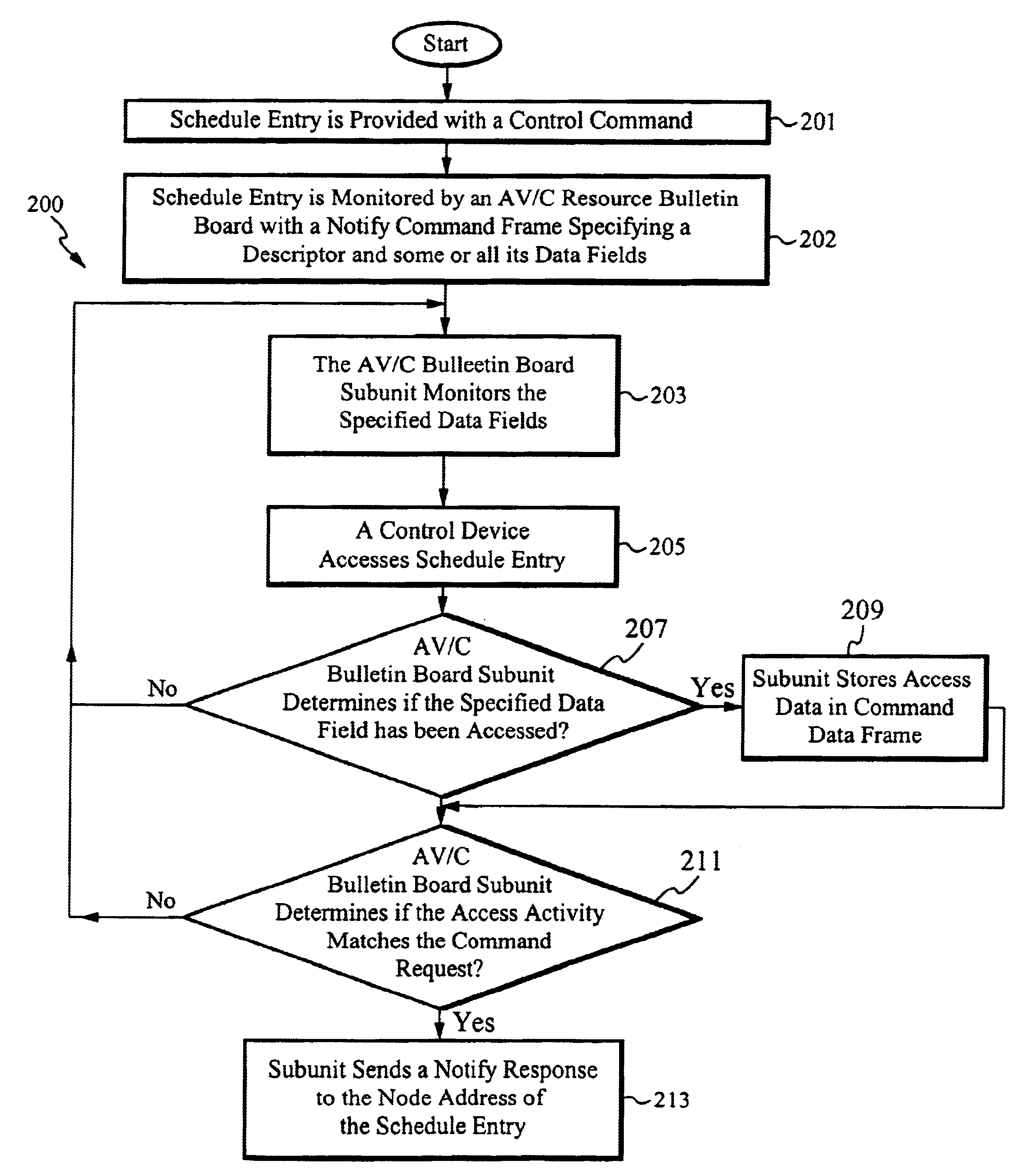
[0011]Each schedule entry stored to the AV / C resource bulletin board subunit specifies the node address of the requesting control device, the resource subunit that is being requested and the time or times that the resource is being scheduled. According to the current invention, schedule entries are monitored for access activity after being stored to the AV / C resource schedule bulletin board subunit by an original requesting control device. In the event that the schedule entry is accessed by a competing control device after it has been stored to the resource schedule bulletin board, a notify response is sent to the node address of the original requesting control device which notifies the original requesting control device that the schedule entry has been accessed by the competing control device.
[0012]Preferably, the original requesting control device specifies the data structure or data structures within the schedule entry that are to be monitored. The original requesting control device specifies the data structures that are monitored by providing a corresponding notify command with the schedule entry when the resource request is submitted to the AV / C resource schedule bulletin board. However, it is considered to be within the scope of the invention that the original requesting control device also submits notify commands to the resource schedule bulletin board at any time that schedule entries are stored in the AV / C resource schedule bulletin board subunit of the resource device. It is also preferable that requesting control devices specify the type of access activity that is to be monitored. For example, when a requesting control device submits a write notify command with a schedule entry, then the schedule entry is monitored for write access activity by competing control devices. In the event that a competing control device writes data or deletes portions of the specified data structure within the schedule entry, then a write notify response is sent to the node address of the requesting control device. Similarly, when a requesting control device submits a read notify command with a schedule entry, then the schedule entry is monitored for read access activities by competing control devices. In the event that a competing control device reads the specified data structure within the monitored schedule entry, then a read notify response is be sent to the node address of the requesting control device.
[0013]According to another embodiment of the present invention, schedule entries are automatically monitored for access activity that is performed by competing control control devices. Anytime that a competing control device reads a schedule entry, writes to a schedule entry or otherwise modifies a schedule entry that is stored in the AV / C resource schedule bulletin board subunit, a notify response is sent to the original requesting control device to notify the original requesting control device that the schedule entry has been accessed. The original requesting control device is provided an opportunity to review any modifications made to the schedule entry by the competing control device.
[0014]A notify command data frame, according to the present invention, contains a data field that captures the address of a competing device that accesses the specified data field of the monitored schedule entry. Further, the notify command data frame contains a data field that captures portions of the specified data structure accessed by the competing control device and provides codes representative of the access activity performed by the competing device. The data contained within the notify command frame is preferably stored in the memory unit of the AV / C resource bulletin board subunit to provide a detailed history of the schedule entry and access activities relating thereto.
[0015]A notify response data frame of the present invention provides an alert message to an original requesting control device when the specified data structure of a monitored schedule entries is accessed by a competing control device. According to an alternative embodiment of the present invention, a notify response command also provides the original requesting control device with information about a competing control device and access activity performed on the monitored schedule entry. Accordingly, notify response data frames contain data fields that post the node address of the competing control device and portions of the specified data structure accessed or modified by the competing control device.

Problems solved by technology

Thus, within the current AV / C protocol there is no method to allow control devices within a network to monitor schedule data or to provide a peer-to-peer review of schedule modifications.

Method used


Image

  • Method of and apparatus for communicating data structures between devices in a networking environment
  • Method of and apparatus for communicating data structures between devices in a networking environment
  • Method of and apparatus for communicating data structures between devices in a networking environment

Examples


Embodiment Construction

[0028]A block diagram of an exemplary IEEE 1395-1995 serial bus network including a computer system and a video camera is illustrated in FIG. 1. The computer system 10 includes an associated display 12 and is coupled to the video camera 14 by the IEEE 1395-1995 serial bus cable 16. Video data and associated data are sent between the video camera 14 and the computer 10 over the IEEE 1395-1995 serial bus cable 16.

[0029]A block diagram of the internal components of the computer system 10 is illustrated in FIG. 2. The computer system 10 includes a central processor unit (CPU) 23, a main memory 21, a video memory 25, a mass storage device 24 and an IEEE 1394-1995 interface circuit 19, all coupled together by a conventional bidirectional system bus 29. The interface circuit 19 includes the physical interface circuit 17 for sending and receiving communications over the IEEE 1395-1995 serial bus. The physical interface circuit 17 is coupled to the camera 14 over the IEEE 1395-1995 serial bu...


PUM


Abstract

An architecture, a system and a method monitors data structures over an IEEE 1394-1995 serial bus network. The data structures are portions of entries posted and stored to a descriptor mechanism. A resource request is submitted by a requesting control device to an AV/C resource schedule bulletin board subunit, where request data is stored and posted. The requesting control device submits a corresponding notify command data frame to the AV/C bulletin board subunit. When a competing control device performs a specified type of access activity on a specified data structure, the bulletin board subunit sends a notify response frame to the original requesting control device. The notify response frame provides an alert to the original requesting control device that the specified access activity has been performed on the specified data structure by a competing control device.

Description

FIELD OF THE INVENTION[0001]The present invention relates to an architecture, a system and a method for communicating data structures between networked devices. More specifically, this invention relates to an architecture, system and method for communicating data structures between devices that are networked with an IEEE 1394 serial bus.BACKGROUND OF THE INVENTION[0002]The IEEE standard, “IEEE Std 1394-1995 Standard For A High Performance Serial Bus,” is an international standard for implementing an inexpensive high-speed serial bus architecture which supports both asynchronous and isochronous format data transfers. Isochronous data transfers are real-time transfers which take place such that the time intervals between significant instances have the same duration at both the transmitting and receiving applications. Each packet of data transferred isochronously is transferred in its own time period. An example of an ideal application for the transfer of data isochronously would be fr...

Claims


Application Information

Patent Timeline
Patent Type & Authority Patents(United States)
IPC IPC(8): G06F15/16G06F15/173G06F13/00H04L12/28H04L29/06H04L29/08
CPCH04L12/2803H04L12/2827H04L67/325H04L63/1408H04L2012/2849H04L67/62
Inventor BRELIN, JON EBBE
Owner SONY CORP
Why Eureka
Try Eureka