Enhanced debug scheme for LBIST

a debug scheme and lbist technology, applied in the field of circuits, can solve the problems of unpredictability of signature changes, difficulty in further debugging beyond this point, and inability to identify when other latches are presen

Inactive Publication Date: 2005-05-31
IBM CORP
View PDF7 Cites 58 Cited by
  • Summary
  • Abstract
  • Description
  • Claims
  • Application Information

AI Technical Summary

Benefits of technology

[0008]The present invention provides an enhanced debug circuit for LBIST testing, and provides a method of screening out failures on a bit-by-bit basis, so that a new signature can be obtained, and the test can be continued to higher frequencies. The present invention can determine and identify exactly which timing paths on the chip fail at which frequencies and map out the whole pattern of failures up to an arbitrary frequency, without being stopped at wherever the first failure occurs on the given string. The present invention can also target a specific latch bit in a string, ignoring everything else, to find the worst case failing pattern ending in that latch.

Problems solved by technology

Since the signature doesn't include any detailed information about which latch failed during which pattern, further debugging beyond this point becomes very difficult.
However, as soon as latch “A” starts failing, the signature no longer matches the golden signature, and, as the test frequency is raised, there is no way to identify when other latches start to fail.
There is no way to determine a new “golden” signature which accounts for the failure in latch “A,” since the failure may occur on many of the test patterns, and as the frequency is changed, the number of “failures” changes in an unpredictable way, meaning that the signature changes unpredictably as well.
This is a source of the problem for fault testing in LBIST.

Method used


Image

  • Enhanced debug scheme for LBIST
  • Enhanced debug scheme for LBIST
  • Enhanced debug scheme for LBIST

Examples


Embodiment Construction

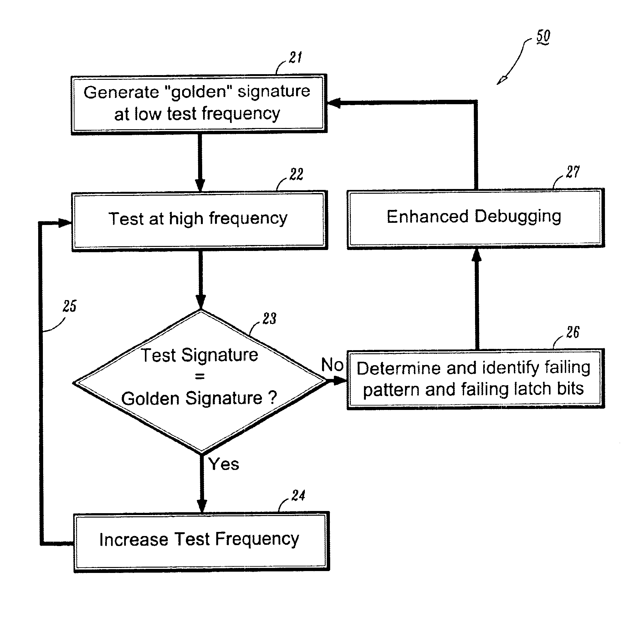
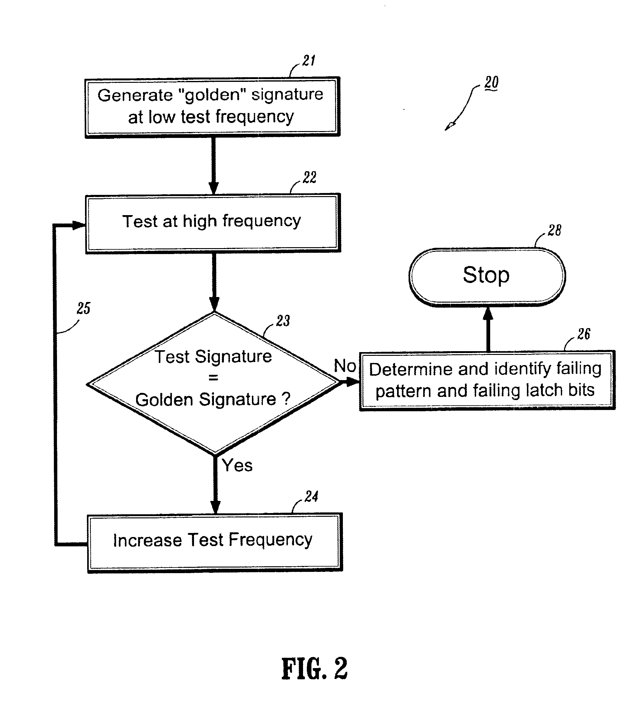
[0020]An enhanced debug circuit is provided for LBIST testing in that the failures are screened out on a bit-by-bit basis, and a new signature is obtained allowing the test to be continued to higher frequencies. The enhanced debug circuit determines and identifies the failures by locating the timing paths and frequencies and mapping out the failures up to an arbitrary frequency, without being stopped at the first failure.

[0021]Referring now in detail to the drawing in which like reference numerals identify similar or identical elements throughout the drawings.

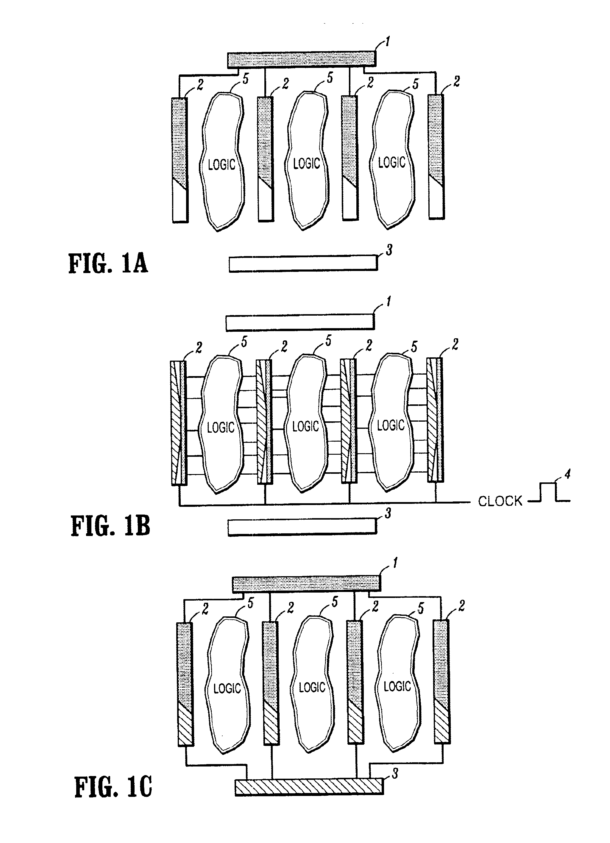
[0022]FIGS. 1A, 1B and 1C are schematic diagrams showing LBIST testing. Generally, the test can be started by providing a pattern generator 1, such as a Pseudo Random Pattern Generator (PRPG), for generating test patterns. The test patterns generated are then passed through parallel scan strings 2 to a signature compression register 3, such as a Multiple Input Shift Register (MIST). In FIG. 1A, test patterns generated from the ...


PUM


Abstract

A device for fault testing in a microprocessor chip provides a LBIST circuit which has a first reference signature. A loading unit is further provided for receiving and outputting a set of masking data. A file unit connected to the loading unit is yet further provided for receiving the masking data. A masking unit connected to the file unit is yet further provided for generating a second reference signature based on the masking data from the file unit and a scanning data from a scan string in the chip. And, a signature logic connected to the output of the masking unit is yet further provided for compressing the second reference signature and inputting the compressed second reference signature to the LBIST circuit, wherein the compressed second reference signature replaces the first reference signature.

Description

BACKGROUND OF THE INVENTION[0001]1. Field of the Invention[0002]The present invention relates to a circuit and more particularly to an enhanced debug circuit for (Logic Built-In Self Test) LBIST testing.[0003]2. Description of the Related Art[0004]LBIST has been extensively used within IBM for testing of faults in chips. Published materials about LBIST include E. B. Eichelbergr and E. Lindbloom, “Random-Pattern Coverage Enhancement and Disgnosis for LSSD Logic Self-Test,”IBM J. Research and Development, Vol. 27, No. 3, May 1983, pp. 265-272; T. W. Williams and E. B. Eichelberger, “Random Patterns Within a Structured Sequential Logic Design,”Digest of Papers 1977 Semiconductor Test Symp, IEEE, October 1977, pp. 19-26; P. Bardell and W. McAnney, “Self-Testing of Multichip Logic Modules,”Digest of Papers 1982, pp. 200-204; D. Komonytsky, “LSI Self-Test Using Level Sensitive Scan Design and Signature Analysis,”Degest of Papers 1982 Int'l Test Conf. IEEE, November 1982, pp. 414-424; E. B...

Claims


Application Information

Patent Timeline
Patent Type & Authority Patents(United States)
IPC IPC(8): G01R31/28G01R31/3185G01R31/3187G01R31/317G06F11/27
CPCG01R31/31705G06F11/27G01R31/3187G01R31/318502
Inventor CHU, SAM GAT-SHANGCLABES, JOACHIM GERHARDGOULET, MICHAEL NORMANDLEBLANC, JOHNNY J.WARNOCK, JAMES DOUGLAS
Owner IBM CORP
Why Eureka
Try Eureka