Tie-in device for the correlation of coordinate systems

a coordinate system and tie-in technology, applied in the field of positioning systems, can solve the problems of limited movement capability, fixture flexibility, and high and achieve the effect of reducing the cost of changes to components or assembly procedures

Inactive Publication Date: 2005-06-07
THE BOEING CO
View PDF8 Cites 94 Cited by
  • Summary
  • Abstract
  • Description
  • Claims
  • Application Information

AI Technical Summary

Benefits of technology

[0009]Tie-in devices are provided according to the present invention for correlating at least two coordinate systems. Each coordinate system is defined by an independent measurement system, and the tie-in devices allow for correl

Problems solved by technology

The fixtures support the components and provide limited movement capability to slide the components together for assembly.
The fixtures typically do not allow for flexibility in the assembly process.
Accordingly, changes to the component or assembly procedure can be expensive.
Furthermore, factory floor space is occupied by fixtures that are not suited for other activities.
These determinations are based on various assumptions, such as assumptions regarding the position of the component relative to the fixture; therefore, the accuracy of such determinations is limited.
In addition, these measurements are taken well in advance of the actual assembly

Method used


Image

  • Tie-in device for the correlation of coordinate systems
  • Tie-in device for the correlation of coordinate systems
  • Tie-in device for the correlation of coordinate systems

Examples


second embodiment

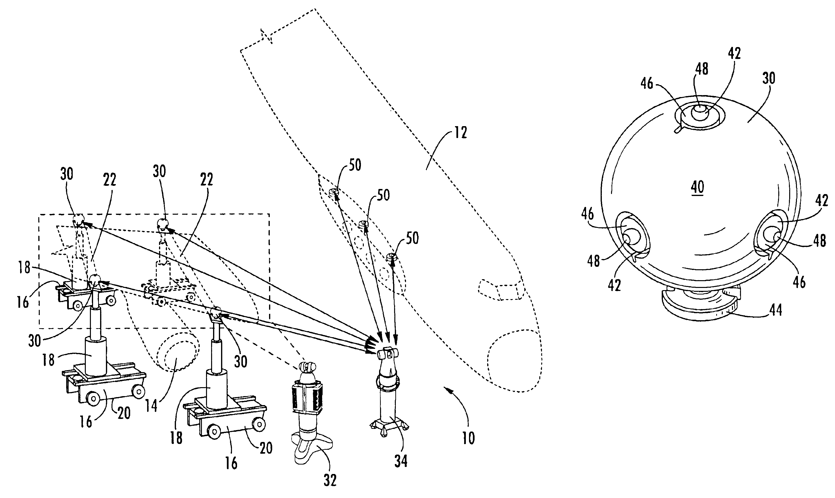
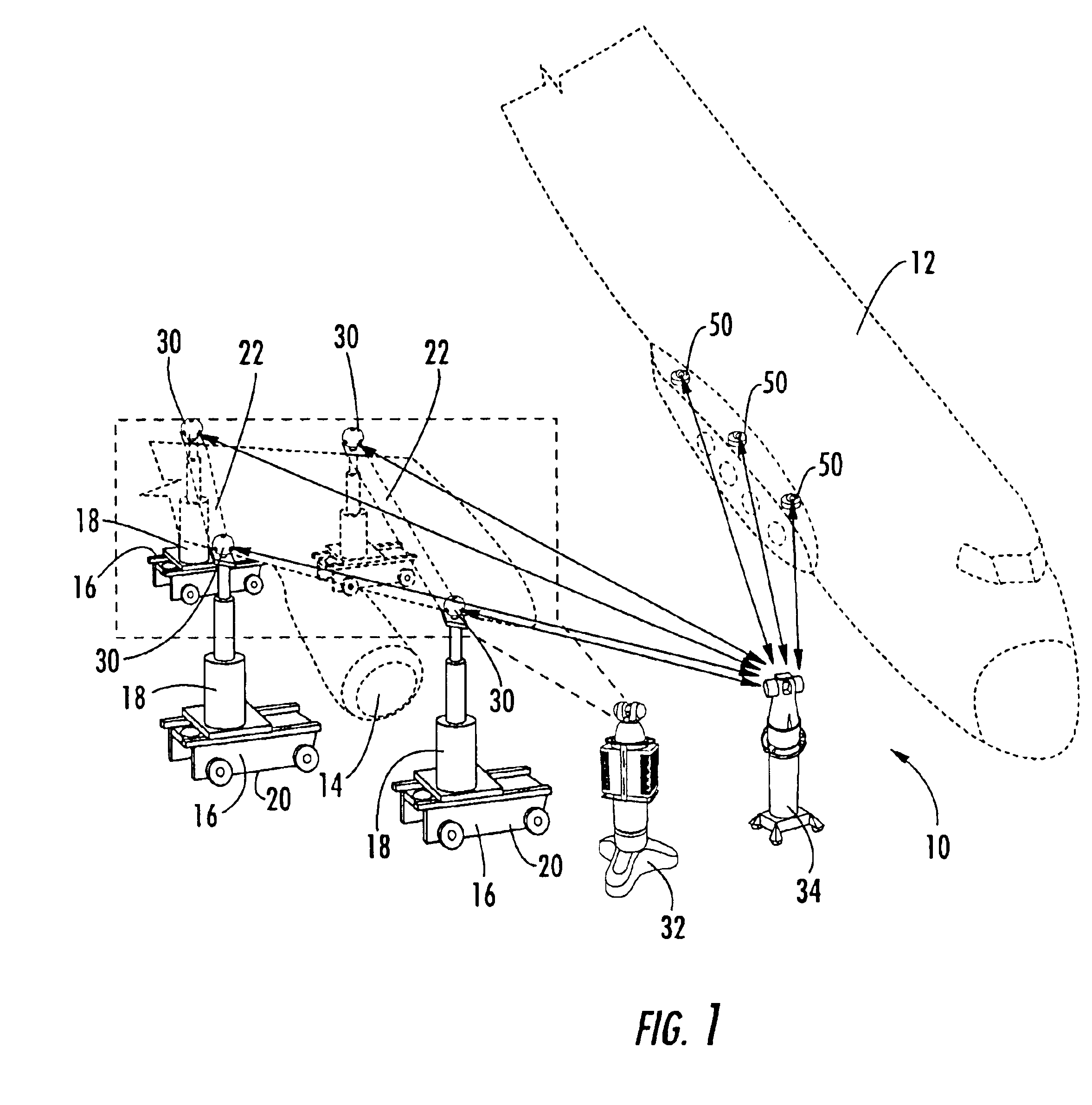
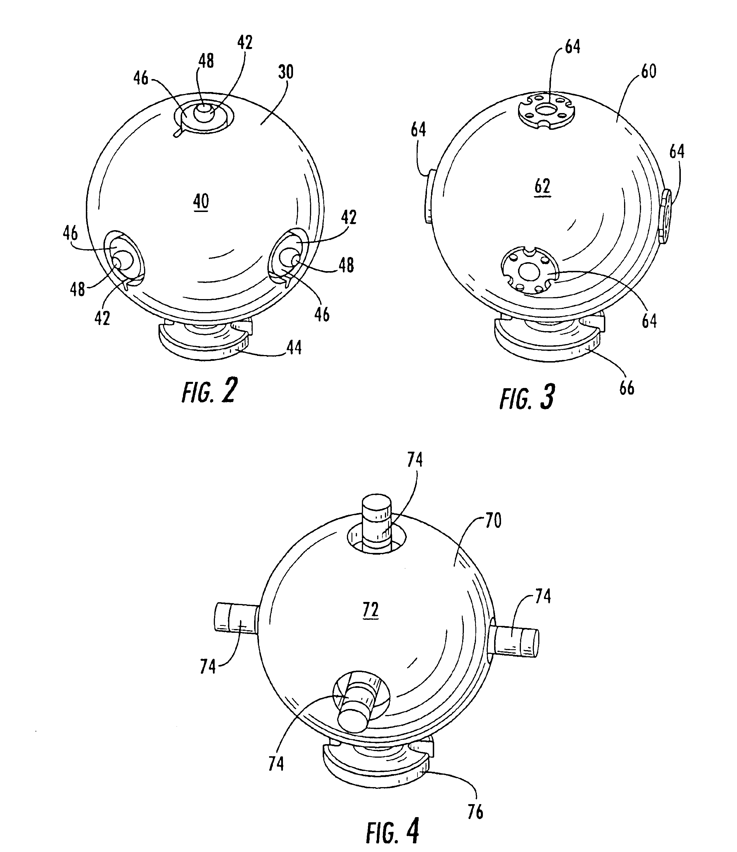
[0040]FIG. 3 illustrates a tie-in device 60 of the present invention, wherein the tie-in device comprises a generally spherical outer surface 62 and at least one target 64 further comprising an infrared flat detector for use with an infrared measurement device as described above. A non-limiting example of an infrared flat detector is the Constellation 3Di™ PATCH DETECTOR, which is also available from Arc Second of Dulles, Va. The tie-in device 60 also comprises a base 66 on the bottom of the generally spherical outer surface 62 to mount the tie-in device to a sufficient surface such that the tie-in device is in a fixed location relative to a component during assembly, as described above.

[0041]The tie-in device 60 of FIG. 3 is advantageously used with a first locating device 32 comprising a laser radar measurement device to map the outer surface 62 of the tie-in device to locate the reference point of the tie-in device in the first coordinate system as described above and with a seco...

third embodiment

[0042]FIG. 4 illustrates a tie-in device 70 of the present invention, wherein the tie-in device comprises a generally spherical outer surface 72 and at least one target 74 further comprising an infrared cylindrical detector for use with an infrared measurement device as described above. A non-limiting example of an infrared cylindrical detector is the Constellation 3Diυ One Detector Tool, 32 Facet Cylindrical Detector End 1, which is also available from Arc Second of Dulles, Va. The tie-in device 70 also comprises a base 76 on the bottom of the generally spherical outer surface 72 to mount the tie-in device, as described above.

[0043]The tie-in device 70 of FIG. 4 is advantageously used with a first locating device 32 comprising a laser radar measurement device to map the outer surface 72 of the tie-in device to locate the reference point of the tie-in device in the first coordinate system as described above and with a second locating device comprising an infrared measurement device ...

fourth embodiment

[0044]FIG. 5 illustrates a tie-in device 80 of the present invention, wherein the tie-in device comprises a generally spherical outer surface 82 and at least one target 84 further comprising an infrared vector bar detector for use with an infrared measurement device as described above. A non-limiting example of an infrared vector bar detector is the Constellation 3Di™ Two Detector Tool, 32 Facet Cylindrical Detector End 2, which is also available from Arc Second of Dulles, Va. The tie-in device 80 also comprises a base 86 on the bottom of the generally spherical outer surface 82 to mount the tie-in device, as described above.

[0045]The tie-in device 80 of FIG. 5 is advantageously used with a first locating device 32 comprising a laser radar measurement device to map the outer surface 82 of the tie-in device to locate the reference point of the tie-in device in the first coordinate system as described above and with a second locating device comprising an infrared measurement device wi...


PUM


Abstract

There is provided a tie-in device for correlating at least two different coordinate systems. The tie-in device comprises an outer surface having a predefined geometric shape, such as a generally spherical surface, located at a first predefined distance from a reference point of the tie-in device, such as the center of the generally spherical surface. The outer surface of the tie-in device is mappable to determine the location of the reference point in a first coordinate system. The tie-in device comprises at least one target located at a second predefined distance from the reference point. The target is locatable in a second coordinate system to determine a location of the reference point in a second coordinate system. The relative locations of the reference point are tied-in, advantageously by processing circuitry, to correlate the first and second coordinate systems.

Description

BACKGROUND OF THE INVENTION[0001]1. Field of the Invention[0002]The present invention is related to positioning systems, and more particularly, to tie-in devices for the correlation of two or more coordinate systems to facilitate positioning of a component.[0003]2. Description of Related Art[0004]Assembly of large structures, such as aircraft, requires the use of large-scale measurement systems to ensure proper assembly of the structures. Components of these large structures are typically assembled using large steel holding fixtures that are by necessity rigid and fixed to the factory floor. The fixtures support the components and provide limited movement capability to slide the components together for assembly. The fixtures require periodic measurement, or surveying, to ensure that the fixture is in proper alignment for the specialized assembly procedure. The fixtures typically do not allow for flexibility in the assembly process. For example, each fixture typically requires a spec...

Claims


Application Information

Patent Timeline
IPC IPC(8): G01B11/26G01B9/02G01B21/04G01B21/24
CPCG01B21/24G01B21/045
Inventor COBB, JAMES M.DELAND, JAMES A.NIELSEN, TIMOTHY G.
Owner THE BOEING CO
Why Eureka
Try Eureka