Fuel injection control method for diesel engine and regenerative control method for exhaust gas after treatment device

a technology of regenerative control and diesel engine, which is applied in the direction of mechanical equipment, electric control, machines/engines, etc., can solve the problems of increasing the size and cost of the system, deteriorating fuel efficiency, and difficult regeneration control, so as to suppress the variation in engine speed and torque, low load operation, and the effect of reducing the drivability

Inactive Publication Date: 2005-06-07
ISUZU MOTORS LTD
View PDF26 Cites 85 Cited by
  • Summary
  • Abstract
  • Description
  • Claims
  • Application Information

AI Technical Summary

Benefits of technology

[0041]Another object is to provide a regeneration method for continuous regeneration type DPF system, allowing to rise the exhaust gas temperature, oxidize and eliminate PM, through the engine fuel injection control, even during an engine operation state with a low exhaust gas temperature such as idling operation, extremely low load operation or the like, in a continuous regeneration type DPF system.
[0088]Therefore, the rising of exhaust gas pressure can be controlled, because the filter can be regenerated any time. Consequently, generation of engine stole or other inconveniences due to the exhaust pressure rising can be avoided. Furthermore, as excessive accumulation of PM can be avoided, the filter melting damage which occurs easily during the PM oxidation following this excessive accumulation of PM can be prevented.

Problems solved by technology

However, this filter for catching PM is clogged along the trap of PM, and the exhaust gas pressure (exhaust gas pressure) rises as the trapped amount of PM increases, it is required thereby to eliminate PM from this DPF, and therefore, several methods and systems have been developed.
Among them, there is a system for eliminating PM by combustion through the heating of the filter with an electric heater or a burner, or back washing by flowing the air in the opposite direction; however, in the case of these systems, the fuel efficiency deteriorates, because PM is burned by supplying heating energy from outside, and the regeneration control is difficult.
In addition, in the case of adopting these systems, often two lines of exhaust passage provided with DPF are installed, PM trap and filter regeneration are repeated alternately, thereby tending to increase the size and cost of the system.
However, even in these continuous regeneration type DPF systems, it is still necessary to rise the exhaust gas temperature to the order of 350° C., and the aforementioned reaction does not occur, and the filter can not be regenerated by PM oxidation in an engine operation state with a low exhaust gas temperature such as idling operation, extremely low load operation or the like, and PM continues to be accumulated in the filter, causing the problem of filter clogging.
For instance, in the idling operation, low speed or extremely low load operation when the engine break is operated on the downhill, the fuel is burned scarcely, a low temperature exhaust gas flows into the continuous regeneration type DPF apparatus, lowering the catalyst temperature and deteriorating the catalyst activity.
If the idling or extremely low load engine operation is sustained, PM trap progresses without supply of a hot exhaust gas that can oxidize and eliminate PM; therefore, PM can not be oxidized and eliminated while PM trap continues, resulting in the progress of filter clogging.
This progress of filter clogging increases the exhaust gas pressure and deteriorates the fuel efficiency and, moreover, when the exhaust gas pressure rises excessively along with the progress of filter clogging, the engine will stop, and if things come to the worst, it will develop to the disability of restart.
Therefore, it is planned to rise the exhaust gas temperature by retarding the injection timing, in the engine fuel injection; however, a misfire of injected fuel may be provoked if it is tried to rise the exhaust gas temperature by retarding considerably the injection timing, a limit occurs in the injection timing retarding angle, leading to the occurrence of a limit for the exhaust gas temperature rising, and the range of possible temperature rising comes to be reduced.
Nevertheless, concerning this main injection retard, there are problems of misfire, deterioration in output torque and fuel efficiency as explained below.
Moreover, there is a case where the injection quantity is reduced in order to intend to optimize the main injection quantity in respect to the required exhaust gas temperature, in order to improve the fuel efficiency, the kindling charcoal becomes insufficient and flames off if the pilot injection quantity of that moment is constant.
Because of these problems of misfire, a limit is developed in the rising of exhaust gas temperature, and, the decrease of the oxygen concentration becomes unable to be achieved.
Also, as for torque output, when this retard control of main injection is performed, the engine output torque lowers as the combustion of the main injection is delayed, making impossible to maintain a high output torque, so there is a problem that this retard control of main injection can not be used in the case of desiring to maintain an output torque.
However, if it is tried to maintain a combustion flame until the timing when the main injection is injected, only by a single sub injection, it becomes necessary to increase the fuel injection quantity in this sub injection, causing the problem of fuel efficiency deterioration.
At the same time, torque is generated by this sub injection, deteriorating the drivability.

Method used


Image

  • Fuel injection control method for diesel engine and regenerative control method for exhaust gas after treatment device
  • Fuel injection control method for diesel engine and regenerative control method for exhaust gas after treatment device
  • Fuel injection control method for diesel engine and regenerative control method for exhaust gas after treatment device

Examples


third embodiment

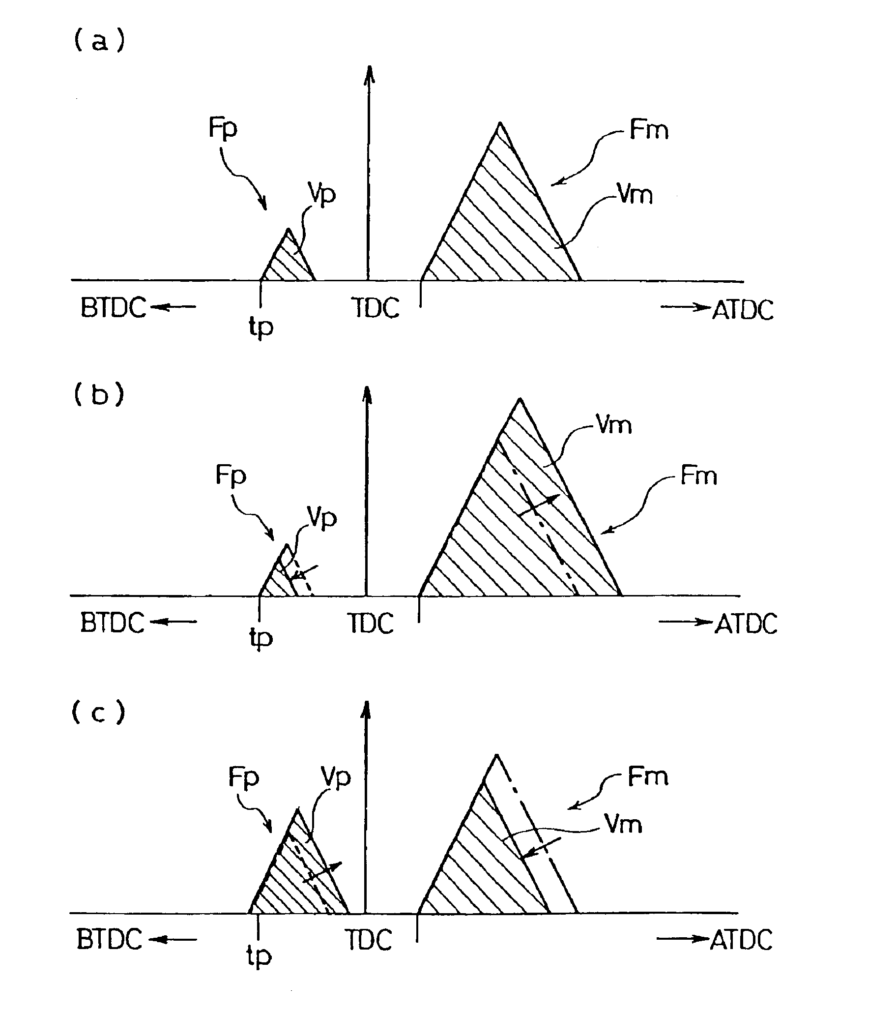
[0154]In the diesel engine fuel injection control method of the third embodiment concerning the injection quantity of the pilot injection and the injection quantity of the main injection, pilot injection Fp and main injection Fm as shown in FIG. 6(a) are performed during the execution of the normal pilot injection. The injection quantity of this pilot injection Fp is a prescribed value and, a previously established fixed quantity.

[0155]There, the injection quantity of the main injection Fm is increased / decreased when it becomes necessary to rise the exhaust gas temperature, or, generate temporally an exhaust gas of reductive atmosphere by lowering the oxygen concentration in the exhaust gas, in order to rise the catalyst temperature of the exhaust gas post-treatment apparatus, regenerate NOx occlusion reduction type catalyst, or regenerate the filter by burning and eliminating PM caught by the DPF.

[0156]For this increase / decrease of the injection quantity of the main injection Fm, i...

example

[0199]An example of fuel injection control involving a multistage auxiliary injection of the fourth embodiment of the present invention is shown in FIG. 12, while a comparative example of fuel injection control involving a pilot injection of the prior art is shown in FIG. 13. It should be appreciated that the engine operation condition at that time, is 1,000 rpm in engine speed, under no load.

[0200]In the example of fuel injection control involving a multistage auxiliary injection shown in FIG. 12, the first auxiliary injection (injection quantity=2.0 mm3 / st) is performed at 8° ATDC, the second auxiliary injection (injection quantity=3.5 mm3 / st) at 20° ATDC, and the main injection (injection quantity=4.6 mm3 / st) at 33° ATDC, to obtain a inlet exhaust gas temperature of 350° C. and an exit exhaust gas temperature of 410° C. in the DPF apparatus.

[0201]On the other hand, in the comparative example of fuel injection control involving a pilot injection shown in FIG. 13, the pilot injecti...


PUM


Abstract

The present invention concerns an diesel engine fuel injection control, and a regeneration control method of exhaust gas post-treatment apparatus using this fuel injection control, and the engine fuel injection control for performing after injections (Fas, Fam) after a main injection (Fm) for activation and regeneration of the exhaust gas post-treatment apparatus, through the rising of diesel engine exhaust gas temperature or the decrease of the oxygen concentration in the exhaust gas, is composed to perform the after injections (Fas, Fam) in a range of 40° ATDC to 90° ATDC of the crank angle.Whereby, the main injection can be burned, without misfire, even when the main injection is largely retarded, or, the injection quantity is increased / decreased, and the engine operation can be sustained, by keeping the engine combustion in a good state.

Description

BACKGROUND OF THE INVENTION[0001]1. Field of the Invention[0002]The present invention concerns a fuel injection control method for diesel engine and a regeneration control method of exhaust post-treatment apparatus.[0003]More precisely, it concerns an engine fuel injection control method for exhaust gas temperature rising of a diesel engine or for oxygen decrease in the exhaust gas, and a regeneration control method on an exhaust gas post-treatment apparatus such as continuous regeneration type diesel particulate filter system of the like for purifying the exhaust gas by trapping particulate matter, using these fuel injection control methods.[0004]2. Detailed Description of the Prior Art[0005]In the recent fuel injection control technology, as shown in FIG. 14(a), a multistage injection technology has been developed actively by increasing the number of injections, in order to retard the rising of the injection quantity when starting the fuel injection, because, in the accumulator ty...

Claims


Application Information

Patent Timeline
Patent Type & Authority Patents(United States)
IPC IPC(8): F01N3/08F02D41/02F01N3/022F01N3/035F02D41/40F02M45/02
CPCF01N3/035F01N3/0821F01N3/0842F01N3/0885F01N3/103F02D41/0245F02D41/029F02D41/402F02D41/403F02D41/405F02M45/02F01N3/0814Y02T10/26F01N2430/085F02D41/1446F02D41/1454Y02T10/44Y02T10/12Y02T10/40
Inventor TASHIRO, YOSHIHISAIMAI, TAKEHITOSUZUKI, TSUNEOOCHI, NAOFUMIGABE, MASASHI
Owner ISUZU MOTORS LTD
Why Eureka
Try Eureka