Flue gas recirculation system

a flue gas recirculation and recirculation system technology, applied in the direction of lighting and heating apparatus, separation processes, instruments, etc., can solve the problems of fragments being too heavy to be conveyed, affecting the flow rate of flue gas, so as to prevent both the accumulation of particulate matter and excessive corrosion, and reduce the amount of particulate material , the effect of reducing the amount of particulate material

Active Publication Date: 2012-11-01
PRIMEX PROCESS SPECIALISTS
View PDF1 Cites 9 Cited by
  • Summary
  • Abstract
  • Description
  • Claims
  • Application Information

AI Technical Summary

Benefits of technology

[0007]The present invention has been devised to preserve the purpose in the prior art of intentional ambient air ingress to DFGT systems while mitigating its adverse consequences. Generally speaking, this system enables the recirculation of treated flue gas either independently or as a substitute for ambient air at specific points of ingress to the DFGT system, thereby stabilizing approach temperature (and related parameters such as reagent consumption and pollutant emission rate) and preventing both the accumulation of particulate matter and excessive corrosion associated with ambient air ingress. This recirculation is accomplished by extracting a fraction of treated flue gas from the induced draft fan outlet and directing it to the absorber vessel or other areas of the DFGT system at a controlled rate through an insulated duct. This recirculation provides the desired turbulence within remote regions of the DFGT system to reduce the amount of particulate material that may otherwise settle and accumulate in these regions, thereby causing particulate matter to be conveyed to the particulate removal device. Insofar as critical properties such as temperature and humidity of the recirculated flue gas are approximately equal to those of flue gas in the absorber vessel, the intended purpose of ambient air ingress is thus preserved while its adverse effects are substantially eliminated.
[0008]Furthermore, in one embodiment of the present invention, removal of accumulated particulate matter directly from the absorber vessel is enabled without permitting ambient air ingress. Particulate matter tends to accumulate on the absorber vessel wall due to localized approach temperature deviations for reasons other than ambient air ingress, such as temperature control system failures, combustion process upsets, boiler tube leaks and inadequate insulation. In these instances, accumulation of particulate matter continues until other forces, such as gravity or flue gas impingement, cause larger fragments to break away from the absorber wall. These larger fragments may be too heavy to be conveyed in the gas stream toward the particulate removal device; therefore some fragments accumulate in the absorber vessel and must be discharged by means other than the particulate removal device. In the prior art, those means typically include a conical hopper with a discharge isolation valve. This isolation valve is opened fully on an intermittent basis to permit the discharge of fragments by gravity for disposal, during which ambient air enters the absorber vessel. Whereas, in accordance with one embodiment of the invention, a transition piece containment vessel (hereinafter “accumulator”) is employed, to which are attached two isolation valves in series. In this embodiment, one of the two isolation valves is always closed, thereby substantially eliminating ambient air ingress while permitting the intermittent discharge of heavy fragments by gravity for disposal. In yet another embodiment of the invention, the portion of the recirculated flue gas may be redirected to other points along the flue gas stream for example at the particulate removal device having a receptacle for the accumulation of particulate matter removed from the flue gas stream. The ducting and recirculated flue gas may be directed to either the absorber vessel or the particulate removal device or both, or any other point or points along the path of the flue gas stream.
[0009]More specifically, the Applicant has invented a control system for mitigating the adverse consequences related to ambient air ingress in a DFGT system that includes an absorber vessel and provisions, such as a hopper located at the base of the absorber, for receiving settled particulate matter from the flue gas. The flue gas is carried from the vessel through ducting (hereinafter “flue gas conduit”) to a downstream device for removing particulate matter entrained in the flue gas. The flue gas conduit then continues from the particulate removal device to a fan in the conduit which induces the flue gas to flow through the absorber vessel and particulate removal device. A recirculation duct is in communication with the flue gas conduit downstream of the fan that enables flue gas to flow through the recirculation duct back to points upstream of the fan. The recirculation duct is insulated to minimize heat loss. A damper located in the recirculation duct is provided to control and maintain the flue gas flow rate at a volume sufficient to suspend and convey particulate matter which may otherwise settle by gravity in the DFGT system.
[0011]It is therefore the main object of the invention to mitigate the adverse consequences related to ambient air ingress in a DFGT system such as pollutant emission rate variations and excessive reagent consumption. It is another object of the present invention to reduce other adverse effects of ambient air ingress on DFGT system operation such as particulate matter accumulation and corrosion. It is a further object of the invention to provide a control system in which heavy fragments of particulate matter settled in the absorber can be systematically removed without the admittance of ambient air to the absorber vessel that may otherwise adversely affect approach temperature, particulate matter accumulation and corrosion in the DFGT system.

Problems solved by technology

Particulate matter tends to accumulate on the absorber vessel wall due to localized approach temperature deviations for reasons other than ambient air ingress, such as temperature control system failures, combustion process upsets, boiler tube leaks and inadequate insulation.
These larger fragments may be too heavy to be conveyed in the gas stream toward the particulate removal device; therefore some fragments accumulate in the absorber vessel and must be discharged by means other than the particulate removal device.

Method used


Image

  • Flue gas recirculation system
  • Flue gas recirculation system
  • Flue gas recirculation system

Examples


Embodiment Construction

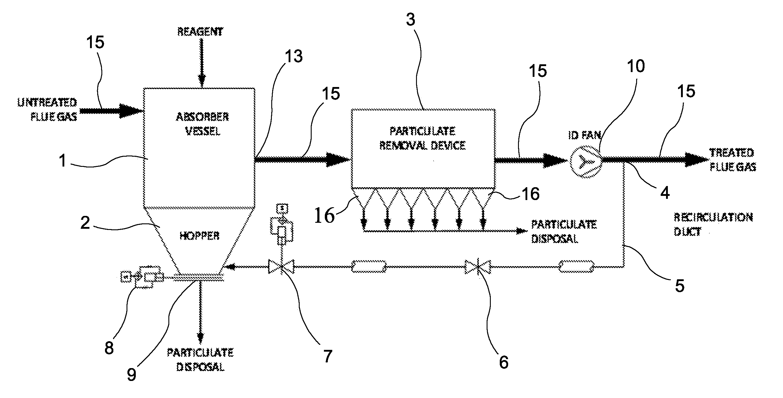
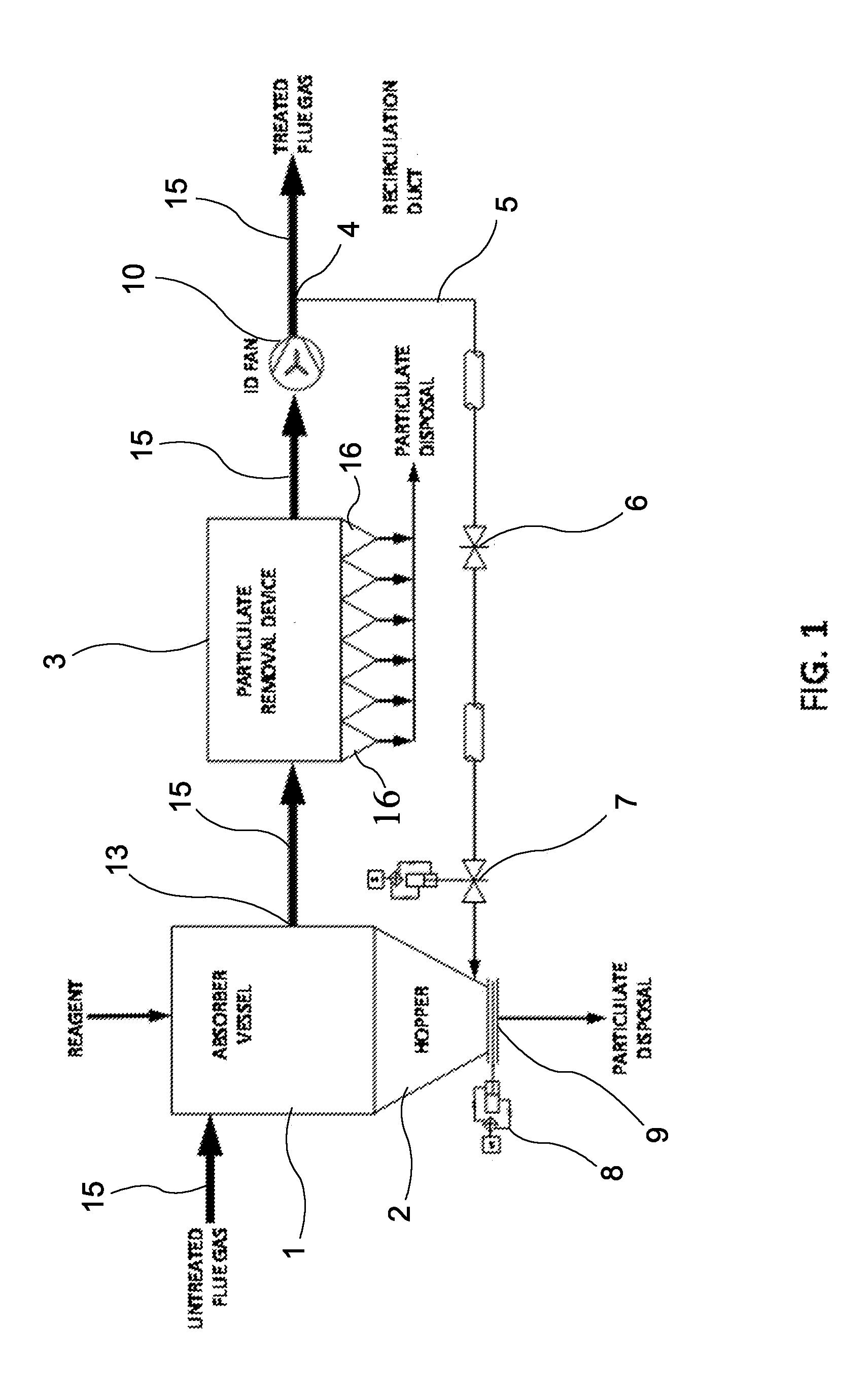
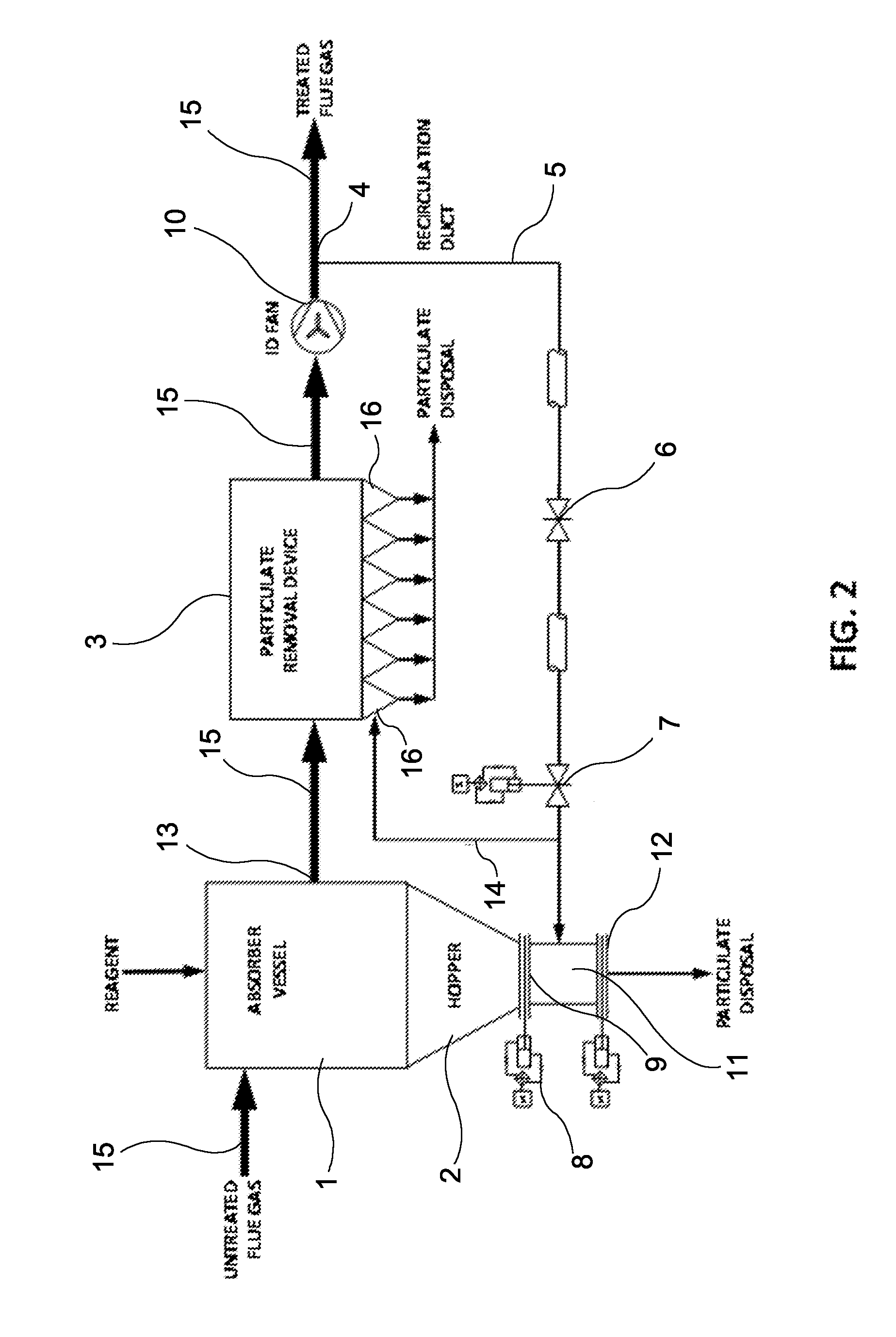
[0016]Referring now to FIG. 1, a DFGT system is illustrated which depicts one embodiment of the present invention. In the previously described DFGT process, untreated flue gas is introduced into an absorber vessel 1 where it is brought into contact with a reagent that is injected into the flue gas stream. Pollutants react with the reagent in the absorber vessel to produce solid particulate matter suspended in the flue gas stream which travels along its path directed by flue gas conduit 15 as it is processed. The flue gas stream containing particulate matter then exits the vessel at the absorber outlet 13 and passes through a flue gas conduit to a fabric filter or electrostatic precipitator unit 3 to remove the particulate matter from the flue gas stream for disposal. Passage of the flue gas stream from the absorber vessel inlet through the absorber vessel and particulate removal device 3 is induced by a fan 10 located downstream of the filter unit through a flue gas conduit 15 shown...


PUM

PropertyMeasurementUnit
thicknessaaaaaaaaaa
thicknessaaaaaaaaaa
temperaturesaaaaaaaaaa

Abstract

Recirculation of treated flue gas either independently or as a substitute for ambient air at specific points of ingress in a flue gas treatment system is provided to stabilize approach temperature and related parameters such as reagent consumption and pollution admission rate preventing both the accumulation of particulate matter and excessive corrosion associated with ambient air ingress. This recirculation provides a desired turbulence within remote regions of the flue gas treatment system to reduce the amount of particulate matter that may otherwise settle and accumulate in the absorber vessel or other areas of the system thereby causing particulate matter to be conveyed to the particulate removal device.

Description

FIELD OF THE INVENTION[0001]This invention relates to air quality control systems, the principal purpose of which is to remove pollutants from the flue gas generated during combustion of solid fuels such as coal, wood products and municipal solid waste. More specifically, this invention relates to dry, circulating dry, semi-dry or spray dryer type flue gas treatment (hereinafter “DFGT”) systems, also commonly referred to as dry scrubber systems.BACKGROUND OF THE INVENTION[0002]The combustion of solid fuels at power generating and waste disposal facilities commonly produces air pollutants such as sulfur dioxide, hydrogen chloride and mercury. In a typical DFGT process, an absorber vessel is located downstream of the combustion process into which the gaseous product of combustion (“flue gas”) and a reagent, such as calcium hydroxide, are directed and intermingled. Pollutants then react with the reagent in the absorber vessel to produce solid particles suspended in the flue gas stream....

Claims


Application Information

Patent Timeline
Patent Type & Authority Applications(United States)
IPC IPC(8): B01D53/79B01D50/00B01D53/34
CPCB01D53/83B01D2257/2045B01D2257/302B01D2257/602
Inventor NICHOLSON, STEWART
Owner PRIMEX PROCESS SPECIALISTS
Why Eureka
Try Eureka