Methods and devices for use in performing pulmonary procedures

a pulmonary procedure and pulmonary tube technology, applied in the direction of prosthesis, application, functional valve type, etc., can solve the problems of less tone, inability to maintain the narrow airway open, and reduce the ability of one or both lungs to fully expel air

Inactive Publication Date: 2005-06-07
PULMONX
View PDF186 Cites 193 Cited by
  • Summary
  • Abstract
  • Description
  • Claims
  • Application Information

AI Technical Summary

Benefits of technology

[0014]In another embodiment, there is disclosed a method for treating a patient's lung, the method comprising steps of selecting a hollow structure in a patient's lung, the hollow structure defining a pathway for conducting fluid flow in at least first and second directions, applying suction to draw fluid through the pathway in the first direction, and substantially preventing fluid flow through the pathway in the second direction.

Problems solved by technology

Pulmonary diseases such as emphysema and chronic obstructive pulmonary disease (COPD) reduce the ability of one or both lungs to fully expel air during the exhalation phase of the breathing cycle.
The problem is further compounded by the diseased, less elastic tissue that surrounds the very narrow airways that lead to the alveoli (the air sacs where oxygen-carbon dioxide exchange occurs).
This tissue has less tone than healthy tissue and is typically unable to maintain the narrow airways open until the end of the exhalation cycle.
This traps air in the lungs and exacerbates the already-inefficient breathing cycle.
The trapped air causes the tissue to become hyper-expanded and no longer able to effect efficient oxygen-carbon dioxide exchange.
Applying suction to these narrow airways (a procedure proposed in the literature for deflating the diseased portion of the lung) may collapse the airways due to the surrounding diseased tissue, thereby preventing successful fluid removal.
By taking up more of the pleural space, the hyper-expanded lung tissue reduces the amount of space available to accommodate the healthy, functioning lung tissue.
As a result, the hyper-expanded lung tissue causes inefficient breathing due to its own reduced functionality and because it adversely affects the functionality of adjacent healthy tissue.
The conventional surgical approach is relatively traumatic and invasive, and, like most surgical procedures, is not a viable option for all patients.
The search for new and better treatments underscores the drawbacks associated with existing pulmonary procedures.

Method used


Image

  • Methods and devices for use in performing pulmonary procedures
  • Methods and devices for use in performing pulmonary procedures
  • Methods and devices for use in performing pulmonary procedures

Examples


Embodiment Construction

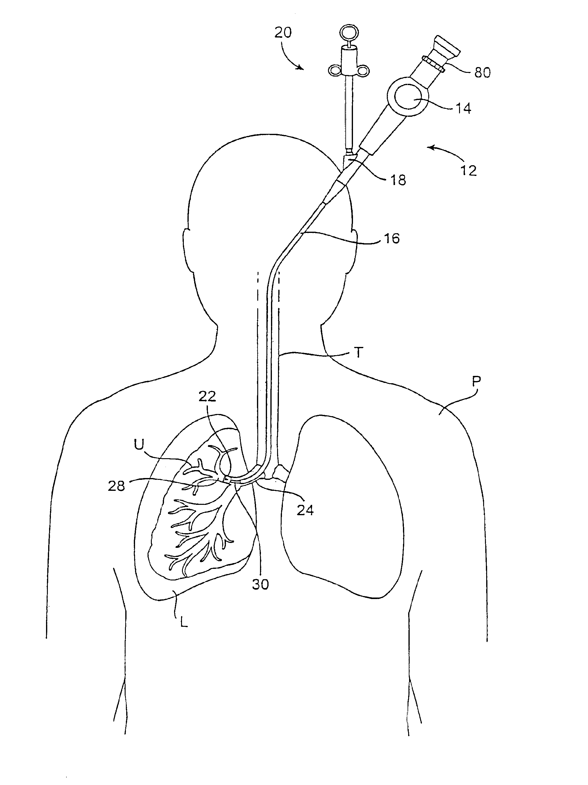
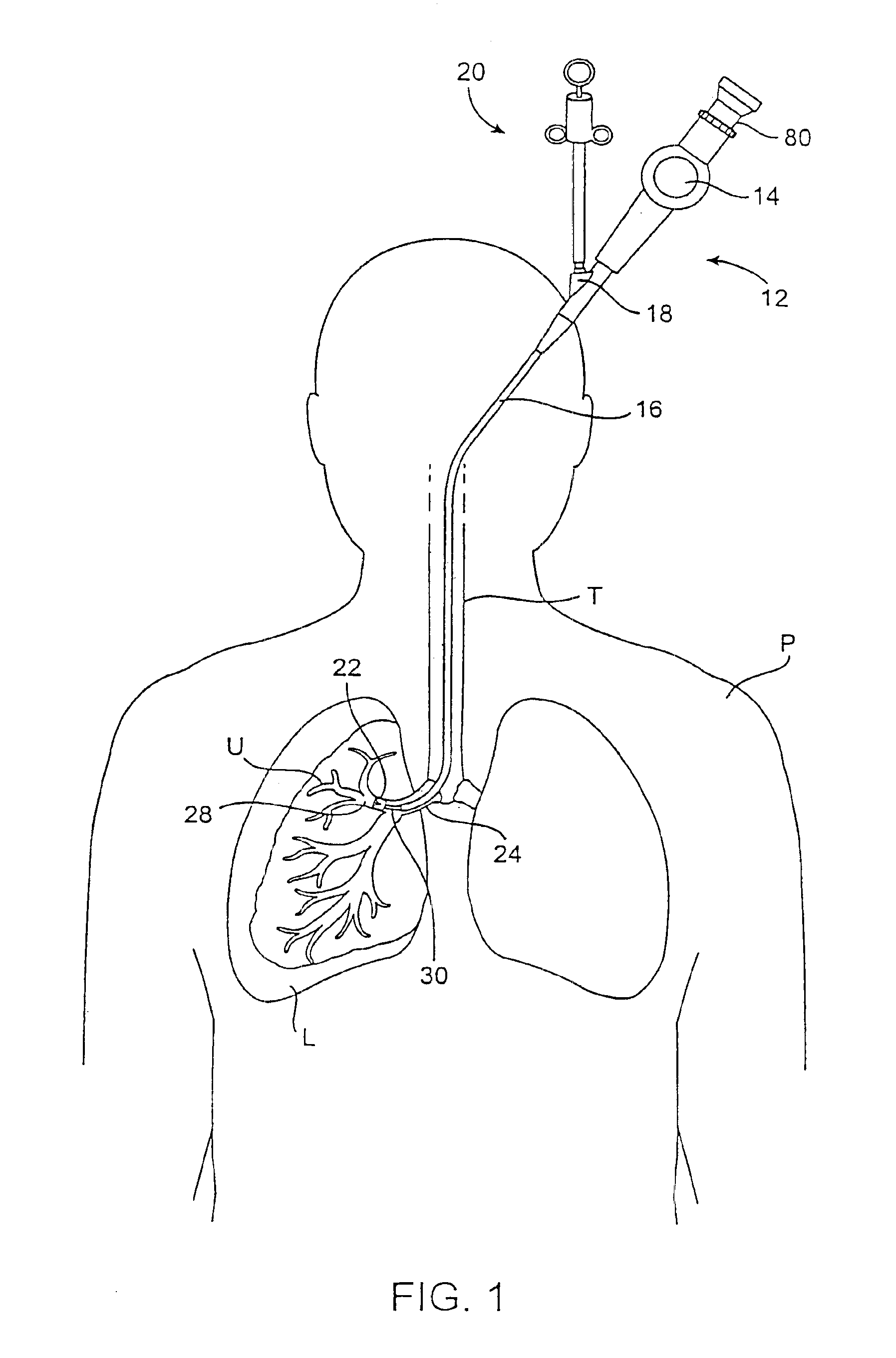
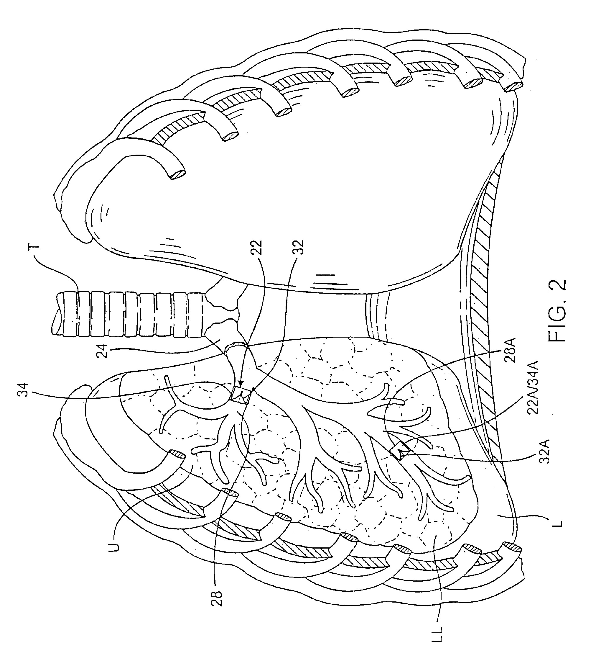
[0062]The present invention provides methods and devices for performing pulmonary procedures, for example, treating various lung diseases such as emphysema and COPD. One preferred embodiment of the invention provides a flow control element that allows fluid flow in a first direction and controls fluid flow in a second direction. As used herein, fluid means gas, liquid, or a combination of a gas(es) and liquid(s). In addition, controlled fluid flow, as used herein, means that the flow is altered in some manner, i.e., the flow is not unimpeded in the second direction. The specific manner in which fluid flow is controlled in the second direction depends on the construction of the flow control element. The flow control element may, for example, completely block, substantially block, limit, meter or regulate fluid flow in the second direction by a valve or other suitable structure.

[0063]As an example, when positioned in a hollow structure in a patient's body, such as a bronchiole in one ...


PUM


Abstract

An implantable flow control element is provided which prevents air from entering an isolated portion of a patient's lung. The element may permit air to escape from the isolated portion so that the element acts like a valve. Systems for implanting pulmonary devices are also provided.

Description

CROSS-REFERENCE TO RELATED APPLICATIONS[0001]This application is a continuation of U.S. patent application Ser. No. 09 / 797,910, filed Mar. 2, 2001, now U.S. Pat. No. 6,694,979 entitled “Methods and Devices for use in Performing Pulmonary Procedures” by Deem et al., which is a continuation-in-part of U.S. patent application Ser. No. 09 / 519,735 filed Mar. 4, 2000, now U.S. Pat. No. 6,679,264 entitled “Methods and Devices for use in Performing Pulmonary Procedures” by Deem et al., the full disclosures of which are incorporated herein by reference.BACKGROUND[0002]1. Field of the Invention[0003]The present invention relates generally to methods and devices for use in performing pulmonary procedures, and more particularly, procedures for treating various diseases of the lungs.[0004]2. Description of the Related Art[0005]Pulmonary diseases such as emphysema and chronic obstructive pulmonary disease (COPD) reduce the ability of one or both lungs to fully expel air during the exhalation phas...

Claims


Application Information

Patent Timeline
Patent Type & Authority Patents(United States)
IPC IPC(8): A61F2/24A61B17/22A61B19/00A61F2/04A61M23/00
CPCA61B17/12104A61F2/24A61F2/2412A61F2/91F16K15/147A61B17/12172A61F2230/0091A61B17/221A61B2017/2215A61B2019/461A61F2/2418A61F2002/043A61B2017/1205A61F2220/0008A61F2220/0016A61F2220/0041A61F2220/005A61F2220/0058A61F2230/005A61F2230/0067A61B2090/061A61F2/2476
Inventor DEEM, MARK E.GIFFORD, III, HANSON S.FRENCH, RONALDSUTTON, DOUGLAS
Owner PULMONX
Why Eureka
Try Eureka