Bi-directionally boosting and internal pressure trapping packing element system

a packing element and bi-directional technology, applied in the direction of sealing/packing, wellbore/well accessories, fluid removal, etc., can solve the problems of not providing creating the potential for at least partial unseating of the packing element, and unable to provide a fluid seal between the liner and the casing, etc., to achieve effective holding

Inactive Publication Date: 2005-06-07
WEATHERFORD TECH HLDG LLC
View PDF100 Cites 39 Cited by
  • Summary
  • Abstract
  • Description
  • Claims
  • Application Information

AI Technical Summary

Benefits of technology

[0014]A novel feature for the packer of the present invention includes a pair of ratchet rings disposed on the outer surface of the booster sleeve. An upper ratchet ring is placed above the packing element, while a lower ratchet ring is disposed below the packing element. The upper ratchet ring is connected to the top sleeve and rides downward along the outer surface of the booster sleeve when the top sleeve is urged downwardly, or the booster sleeve is urged upwardly. Reciprocally, the lower ratchet ring is connected to the bottom sleeve, and rides upwardly along the outer surface of the booster sleeve in response to downward movement of the booster sleeve. Each ratchet ring is configured to ride across serrations on the outer surface of the booster sleeve. In this way, the ratchet rings lock in the relative positions of the top sleeve and the bottom sleeve as they travel across the booster sleeve. These locked positions, in turn, effectuate a more effective holding of the packing element within the annular region.
[0015]Finally, the packer of the present invention may provide slips and associated cones for holding the position of the packer within the casing. In one arrangement, the slips, cones and top sleeve are initially held together by a frangible member such that downward force on the slip ring supplies the needed downward force on the top sleeve in order to expand the packing element from the packer assembly.

Problems solved by technology

However, it does not provide a fluid seal between the liner and the casing.
A disadvantage with known packer systems is the potential for becoming unseated.
In this regard, wellbore pressures existing within the annular region between the liner and the casing string act against the setting mechanisms, creating the potential for at least partial unseating of the packing element.
When the differential pressure approaches or exceeds the initial internal pressure of the packer element, the packing element is compressed further by the differential pressure, thereby causing it to extrude into smaller voids and gaps.
However, the internal pressure of the packer element is now below the initial level because of the volume transfer during extrusion.

Method used


Image

  • Bi-directionally boosting and internal pressure trapping packing element system
  • Bi-directionally boosting and internal pressure trapping packing element system
  • Bi-directionally boosting and internal pressure trapping packing element system

Examples


Embodiment Construction

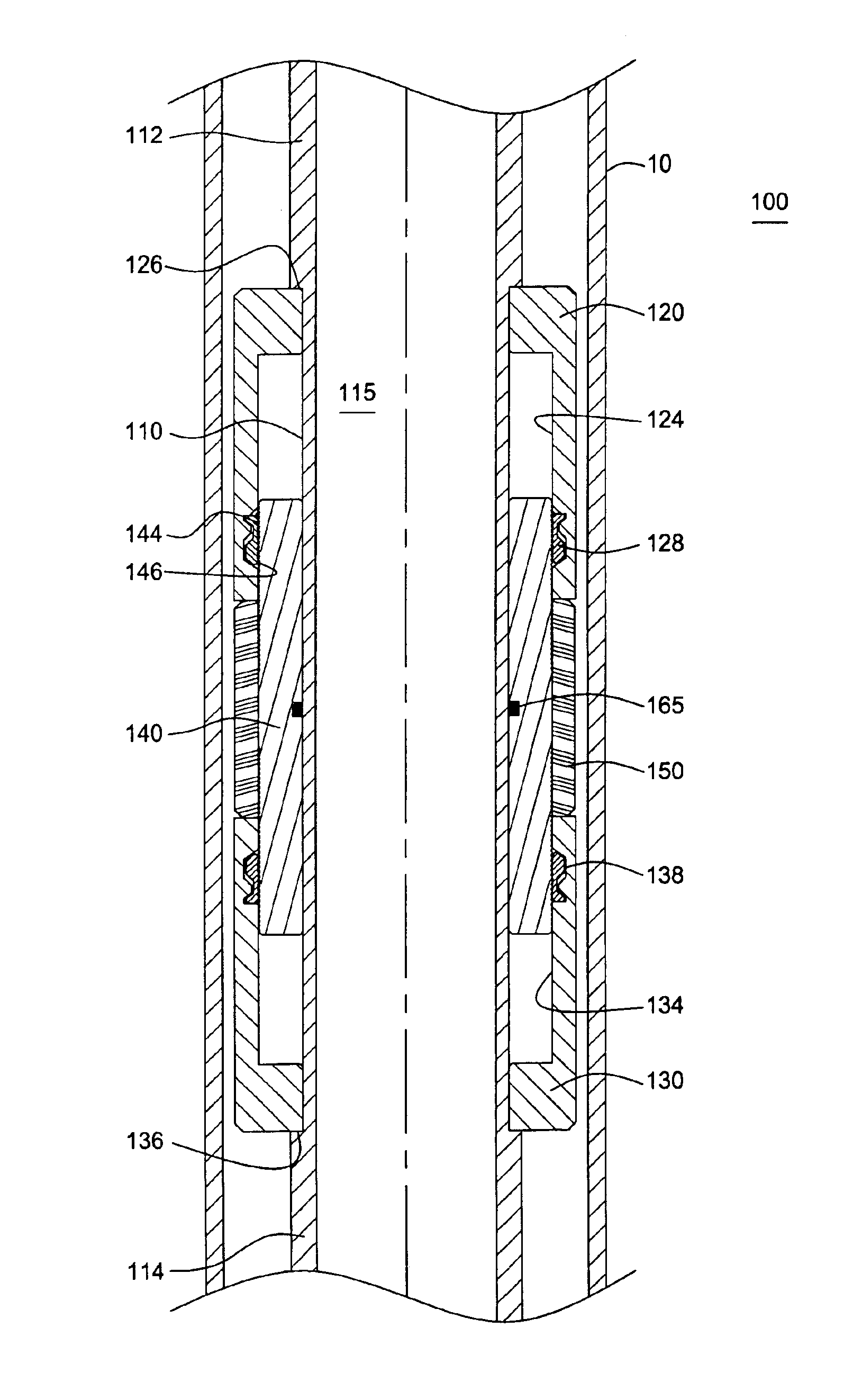
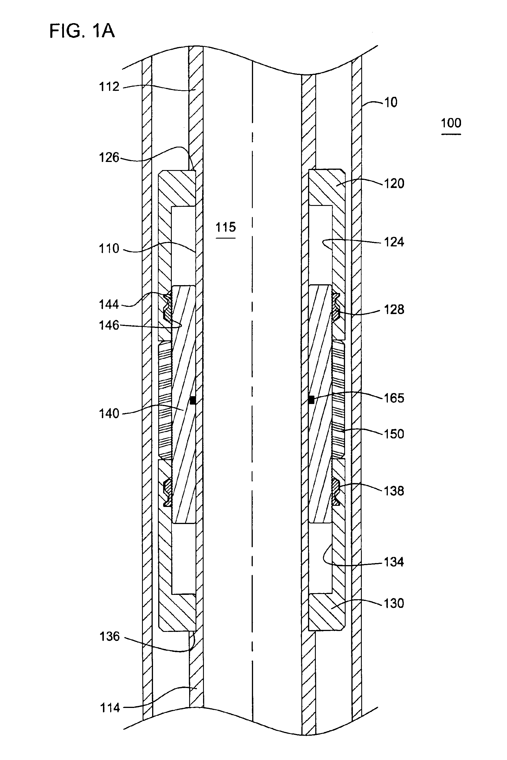
[0028]FIG. 1A presents a cross-sectional view of a packer assembly 100 in accordance with the present invention. The packer 100 has been run into a wellbore (not shown). The packer 100 has been positioned inside a string of casing 10. The packer 100 is designed to be actuated such that a seal is created between the packer 100 and the surrounding casing string 10.

[0029]The packer 100 is run into the wellbore at the upper end of a liner string or other tubular (not shown). Generally, the bottom end of the packer 100 is threadedly connected to a liner hanger (not shown). Those of ordinary skill in the art will understand that the liner hanger is also actuated in order to engage the surrounding upper string of casing 10 and, thereby anchoring the liner below. In this manner, a liner string (not shown) may be suspended from the upper casing string 10.

[0030]In the typical well completion operation, the packer 100 is run into the wellbore along with various other completion tools. For exam...


PUM


Abstract

Present invention is a packer for sealing an annular region in a wellbore. The packer includes a packing element which is held through bi-directional forces. The packer first comprises an inner mandrel. Disposed around the inner mandrel are three tubulars: (1) a top sleeve; (2) a bottom sleeve; and (3) a booster sleeve. A packing element is disposed circumferentially around the outer surface of the booster sleeve. The top sleeve and bottom sleeve each include an upper compression member which rides across the booster sleeve in order to compress the packing element. The packing element is expanded outward from the packer to engage a surrounding string of casing through compressive forces provided by the top and bottom sleeves. Thereafter, differential pressure applied above or below the packer acting on the packer element and booster sleeve may provide additional compression of the packer element.

Description

CROSS-REFERENCE TO RELATED APPLICATIONS[0001]This application claims benefit of U.S. provisional patent application Ser. No. 60 / 340,520, filed Dec. 12, 2001, which is herein incorporated by reference.BACKGROUND OF THE INVENTION[0002]1. Field of the Invention[0003]The present invention generally relates to completion operations in a wellbore. More particularly, the invention relates to a packer for sealing an annular area between two tubular members within a wellbore. More particularly still, the invention relates to a packer having a bi-directionally boosted and held packing element.[0004]2. Description of the Related Art[0005]In the drilling of oil and gas wells, a wellbore is formed using a drill bit that is urged downwardly at a lower end of a drill string. After drilling a predetermined depth, the drill string and bit are removed and the wellbore is lined with a string of casing. An annular area is thus formed between the string of casing and the formation. A cementing operation...

Claims


Application Information

Patent Timeline
Patent Type & Authority Patents(United States)
IPC IPC(8): E21B33/12E21B33/128
CPCE21B33/128
Inventor HIRTH, DAVID E.PEDERSEN, GERALD D.GUDMESTAD, TARALD
Owner WEATHERFORD TECH HLDG LLC
Why Eureka
Try Eureka