
Lateral operator restraint system and position sensor for material handler

a technology for operator restraint and material handler, which is applied in the direction of electric devices, pedestrian/occupant safety arrangements, tractors, etc., can solve the problems of dumping and crowd control of attachments, the inability to utilize auxiliary controls for attachments, and the inability to lift, lowering or telescope the boom

Inactive Publication Date: 2005-06-07
CLARK EQUIP CO INC
View PDF26 Cites 43 Cited by
  • Summary
  • Abstract
  • Description
  • Claims
  • Application Information

AI Technical Summary

Benefits of technology

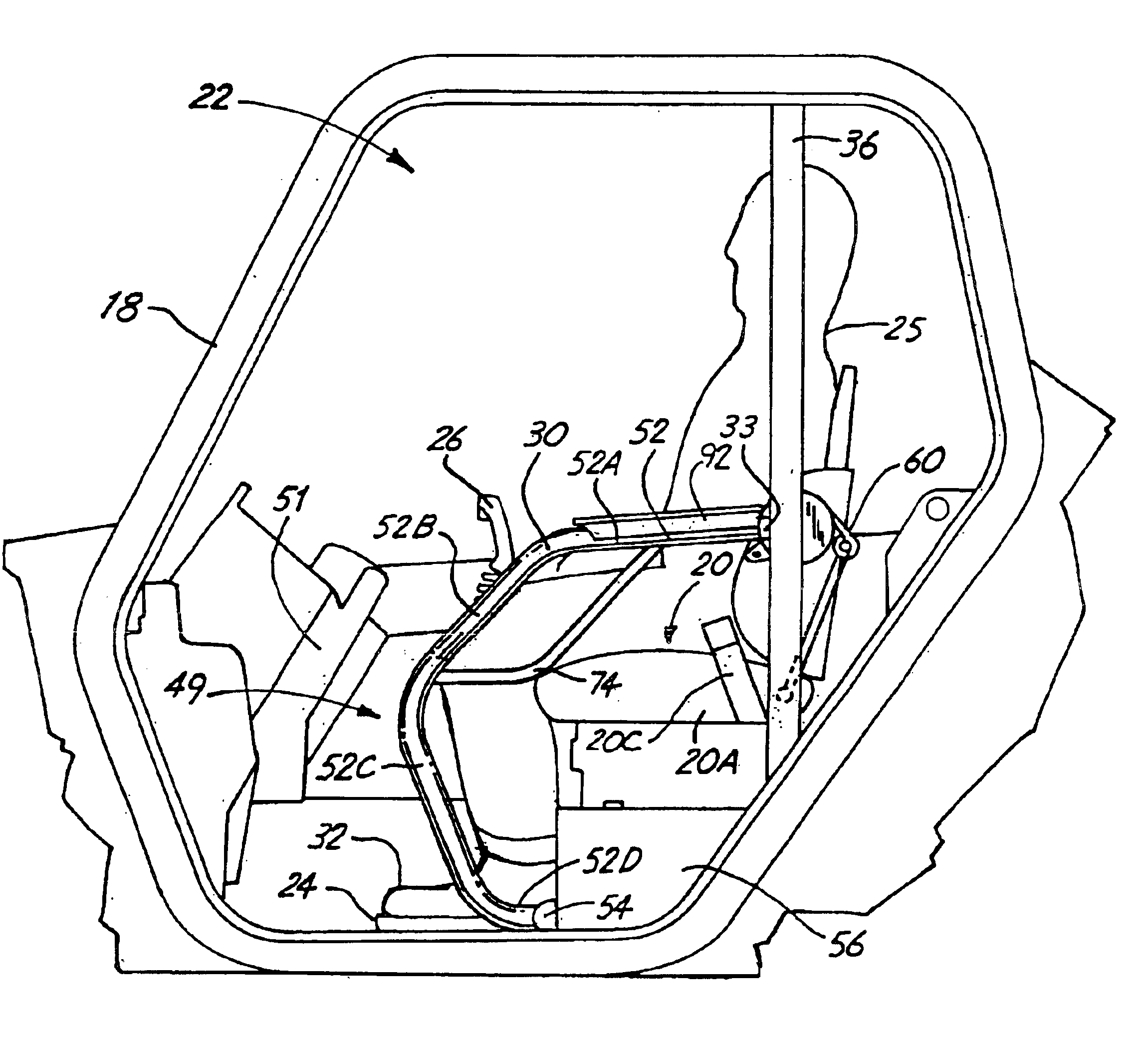
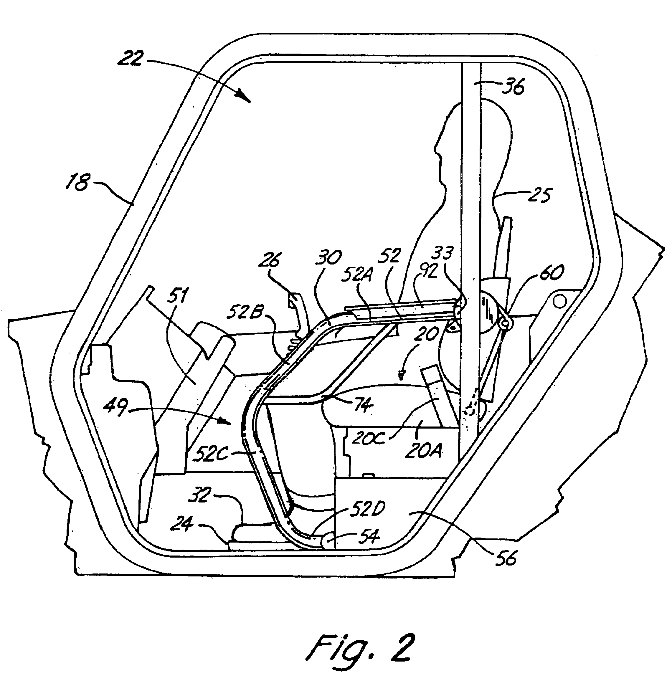
[0004]The present invention relates to a movable bar acting as a lateral operator restraint and has an arm rest portion for operator comfort. The pivoting restraint bar is mounted on the side of an operator's cab of a machine such as a material handler, adjacent to the operator access door opening, and positioned to the exterior side of the operator's seat. The operator restraint bar is oriented for movement from a working position wherein it is located to block lateral movement of the operator and the operator's foot and leg in a direction toward the exterior of the cab, and which can be manually moved upwardly out of the way easily for operator access and egress from the cab. As shown, the restraint bar is pivoted by a mounting linkage or other support arrangement can be used.

Problems solved by technology

This means that the boom cannot be lifted, lowered, or telescoped, and the dump and crowd controls for attachments, and the auxiliary controls for the attachment cannot be utilized.

Method used


Image

  • Lateral operator restraint system and position sensor for material handler
  • Lateral operator restraint system and position sensor for material handler
  • Lateral operator restraint system and position sensor for material handler

Examples


Embodiment Construction

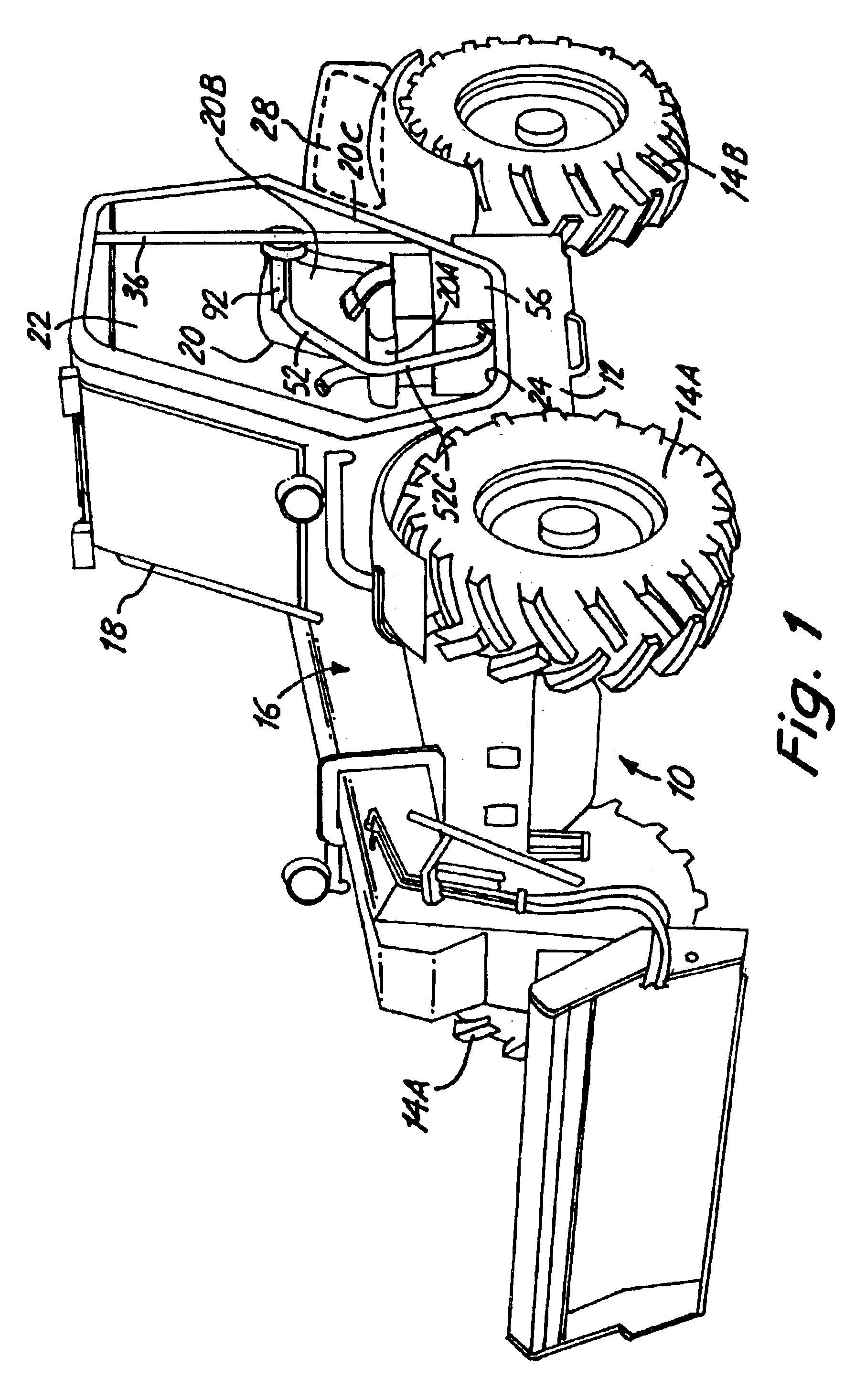
[0019]In FIG. 1, a material handler machine indicated generally at 10, as shown, has a main frame 12, and drive and steering wheels 14A and 14B. The material handler 10 can have two wheel steer, crab steer, or four wheel steer, and generally speaking all four wheels that are shown are powered, for normal operation.

[0020]The material handler frame 12 has a telescoping boom 16 mounted thereon about a pivot at the rear of the frame (not shown) and the boom extends forwardly and overlies the right hand side of the frame. It can be seen that the boom 16 is to the inside of the wheel 14A on the right hand side of the machine oriented with the operator looking forwardly.

[0021]The frame 12 also has an operator's cab or canopy shown generally at 18, which is supported on the frame 12 in a normal manner. In a telescoping boom material handler, the side of the cab adjacent to the boom is generally closed with windows or screens for visibility, so that an operator cannot move into the path of t...


PUM


Abstract

A self-propelled material handler has a pivotally mounted boom on a frame, and a cab that is positioned adjacent the side of the boom. The cab has an operator's entrance and exit opening on a side of the cab, that is positioned to permit an operator to enter and exit the cab and sit on a seat in the cab. A lateral restraint bar is mounted between the seat and the cab opening, and is movable to a working position where it obstructs the cab opening so that portions of the operator cannot be moved outwardly through the cab side opening from the interior, and which pivots to a raised position to permit an operator to pass through the cab opening. When the restraint bar moves away from its working position, a signal is provided to disable machine controls.

Description

[0001]The present application is based on and claims the benefit of U.S. Provisional Patent Application Ser. No. 60 / 429,755, filed Nov. 27, 2002, the content of which is hereby incorporated by reference in its entirety.BACKGROUND OF THE INVENTION[0002]The present invention relates to a lateral restraint system in a cab on a material handler or TOOL CARRIER that moves along side an operator's seat, and is particularly useful to restrain an operator when there is no side door on the cab operator access opening. The lateral restraint system includes a restraint bar and an arm rest on the exterior side of the operator and is movable from a working, operator and leg restraining position to a raised position. The restraint bar pivots upwardly so in its raised position it is out of the way to permit egress and entrance to the cab and the system has a sensor to disable controls when not in a working position. It is preferable that the operator wears a seat belt during operation to avoid inj...

Claims


Application Information

Patent Timeline
Patent Type & Authority Patents(United States)
IPC IPC(8): B60R21/13B60K28/00B60K28/04B66F9/065B66F9/075E02F9/16E02F3/28
CPCB60K28/04B60R21/131E02F9/163B66F9/0655B66F9/07545E02F3/286B60Y2200/22B60Y2200/221B60Y2200/415B60Y2200/41B60N2/753B60N3/023
Inventor MIILLER, KEVIN J.KRIEGER, DANIEL J.CURL, WILLIAM H.PONCET, BERNARDLICHTENBERGER, FREDERIC
Owner CLARK EQUIP CO INC
Learn More