
Air duct outlet with single vane air stream direction control

Inactive Publication Date: 2005-06-07
INT AUTOMOTIVE COMPONENTS GRP NORTH AMERICA INC
View PDF39 Cites 25 Cited by
  • Summary
  • Abstract
  • Description
  • Claims
  • Application Information

AI Technical Summary

Benefits of technology

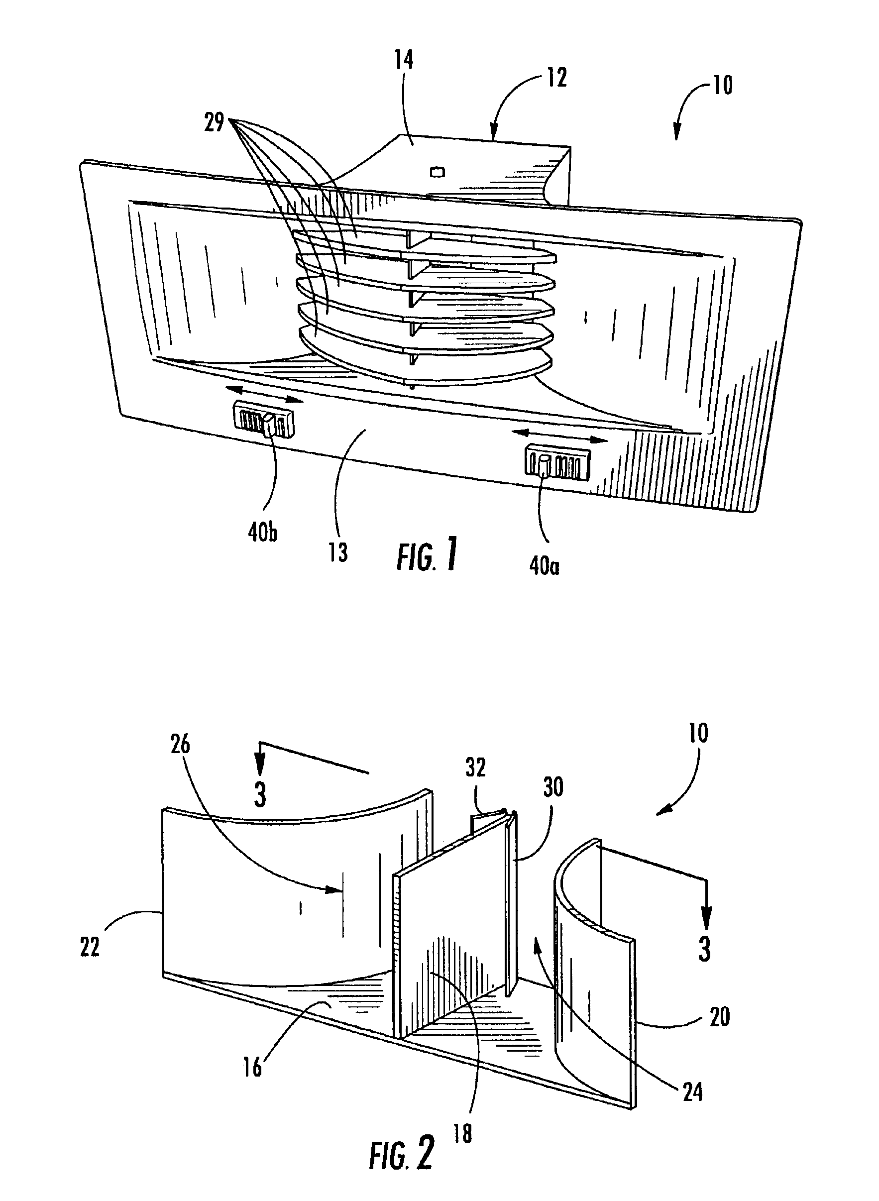
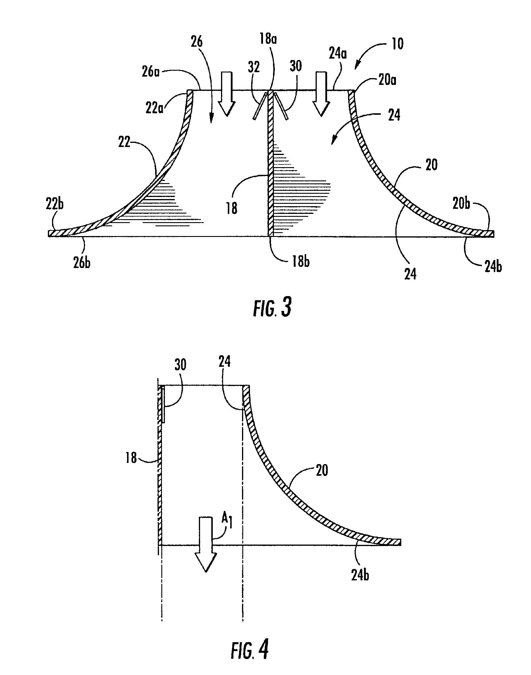
[0005]In view of the above discussion, air duct outlets that allow users to redirect air streams within a wide range of directions and without causing large pressure drops and reduced flow rates are provided. According to embodiments of the present invention, an air duct outlet includes a housing having a planar first wall and a convexly-curved second wall that are in adjacent, spaced-apart relationship and that define an air passageway having an inlet and a flared outlet. A vane is pivotally attached within the air passageway and is movable within a range of positions that are increasingly transverse to the first wall. An air stream flowing through the air passageway is deflected by an amount that increases with each position of the vane in the range such that the air stream adheres to a portion of the second wall via the Coanda effect by an amount that increases with each position of the vane in the range and such that the air stream exits from the outlet in a direction that is increasingly transverse to a direction normal to the outlet.
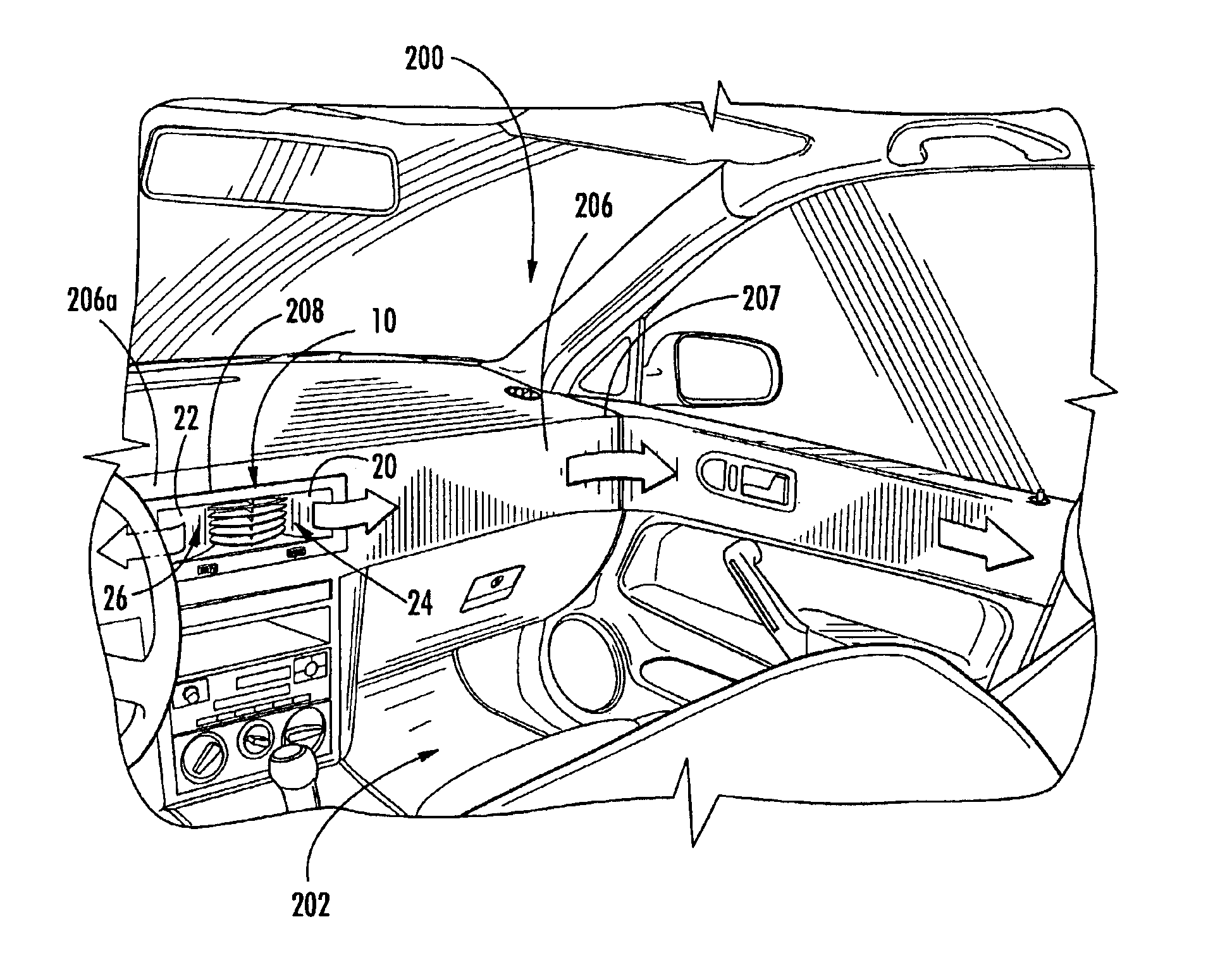
[0007]According to another embodiment of the present invention, air distribution systems for vehicle passenger compartments include an instrument panel having a convexly-curved portion and an opening formed therein in spaced-apart relationship with the convexly-curved portion. An air duct outlet having one or more convexly-curved walls as described above is disposed within the instrument panel opening. Movement of a vane within an air passageway of the air duct outlet to a fully deflected position causes an air stream flowing through the air passageway to adhere via the Coanda effect to a convexly-curved wall of the air duct outlet and to a surface of the instrument panel. The air stream follows the instrument panel surface to the instrument panel convexly-curved portion. The air stream adheres to the convexly-curved portion of the instrument panel and is directed to a remote location of the vehicle passenger compartment.
[0008]Air duct outlets according to embodiments of the present invention allow for improved air flow directability including greatly increased ranges of directability. Moreover, air duct outlets according to embodiments of the present invention can facilitate new and improved styling opportunities for vehicle manufacturers and other manufacturers. Air duct outlets according to embodiments of the present invention are not limited to uses within vehicles (e.g., automobiles, trucks, boats, aircraft, etc.), but may also be utilized in residential and commercial heating, ventilating and air conditioning (HVAC) applications.

Problems solved by technology

While this technology is proven and successful, the louver assemblies can be complex and expensive to manufacture.
Deflection ranges in excess of ±45° typically result in large pressure drops and lower air flow rates, which are undesirable.

Method used


Image

  • Air duct outlet with single vane air stream direction control
  • Air duct outlet with single vane air stream direction control
  • Air duct outlet with single vane air stream direction control

Examples


Embodiment Construction

[0017]The present invention now is described more fully hereinafter with reference to the accompanying drawings, in which preferred embodiments of the invention are shown. This invention may, however, be embodied in many different forms and should not be construed as limited to the embodiments set forth herein; rather, these embodiments are provided so that this disclosure will be thorough and complete, and will fully convey the scope of the invention to those skilled in the art.

[0018]In the drawings, the thickness of lines, layers and regions may be exaggerated for clarity. It will be understood that when an element such as a layer, region, substrate, or panel is referred to as being “on” another element, it can be directly on the other element or intervening elements may also be present. In contrast, when an element is referred to as being “directly on” another element, there are no intervening elements present. It will be understood that when an element is referred to as being “c...


PUM


Abstract

An air duct outlet that allows a user to redirect an air stream within a wide range of directions includes a housing having a planar first wall and a convexly-curved second wall in adjacent, spaced-apart relationship and that define an air passageway having an inlet and a flared outlet. A vane is pivotally attached within the air passageway and is movable within a range of positions that are increasingly transverse to the first wall. An air stream flowing through the air passageway is deflected by an amount that increases with each position of the vane in the range such that the air stream adheres to a portion of the second wall by an amount that increases with each position of the vane in the range and such that the air stream exits from the outlet in a direction that is increasingly transverse to a direction normal to the outlet.

Description

RELATED APPLICATION[0001]This application claims the benefit of U.S. Provisional Application No. 60 / 443,952 filed Jan. 31, 2003, the disclosure of which is incorporated herein by reference in its entirety as if set forth fully herein.FIELD OF THE INVENTION[0002]The present invention relates generally to vehicles and, more particularly, to air duct outlets utilized within vehicles.BACKGROUND OF THE INVENTION[0003]Conventionally, vehicle interiors are provided with one or more air duct outlets which are connected by ducts to an outside air source and / or to a heating and / or air conditioning system that provides cooled and / or heated air. Because it is generally desirable for vehicle occupants to be able to adjust the direction of air flow within a vehicle interior, air duct outlets are typically provided with adjustable vanes or louvers. In addition, air duct outlets may be provided with dampers for allowing vehicle occupants to control the amount of air flowing therethrough.[0004]Conve...

Claims


Application Information

Patent Timeline
IPC IPC(8): B60H1/34F24F13/062F24F13/06F15D1/08
CPCB60H1/3414F24F13/062F24F13/06F15D1/08
Inventor GEHRING, THOMAS F. J.JANKOWSKI, IRENEUSZHAVIDIC, DEJANHESTER, DOUGLAS LIMLEWIS, PETER DOMINIC
Owner INT AUTOMOTIVE COMPONENTS GRP NORTH AMERICA INC
Learn More