Apparatus for separating plastic chips

a sorting apparatus and plastic chip technology, applied in the direction of electrostatic separation, solid separation, chemical apparatus and processes, etc., can solve the problems of affecting continuous processing, affecting the quality of plastic chips, and affecting the separation performance, etc., to achieve high purity and high recovery rate

Inactive Publication Date: 2005-06-07
HITACHI ZOSEN CORP
View PDF7 Cites 31 Cited by
  • Summary
  • Abstract
  • Description
  • Claims
  • Application Information

AI Technical Summary

Benefits of technology

[0016]According to this construction, the upper- and lower-stage electrostatic separating sections, arranged in the vertical direction to electrostatically separate and sort out electrified plastic pieces according to their polarity and electrification amount, are located below the tribo-electrifying device which stirs and tribo-electrifies the plastic pieces, so that plastic pieces attracted to the rotationally movable electrode in the upper-stage electrostatic separating section or following falling trajectories approaching the rotationally movable electrode, are fed to the second electrostatic separating section via the connection section. Most of thes

Problems solved by technology

However, to improve the separation precision of the conventional apparatuses, it is necessary to use long electrode plates to increase the time required for the plastic pieces to pass through the separating electrostatic field, which disadvantageously requires the size of the apparatuses to be increased.
Further, the plastic pieces may adhere to the electrodes, resulting in degraded separation performance, to hinder continuous processing.
FIG. 10 indicates that it is likely that an increase in purity reduces the recovery rate, whereas an increase in recovery rate reduces the purity.
Thus, if plastic pieces are to be recovered according to their material, the rate at which plastic pieces are recovered becomes insufficient to make the separating operation less efficient even if the plastic pieces h

Method used


Image

  • Apparatus for separating plastic chips
  • Apparatus for separating plastic chips
  • Apparatus for separating plastic chips

Examples


first embodiment

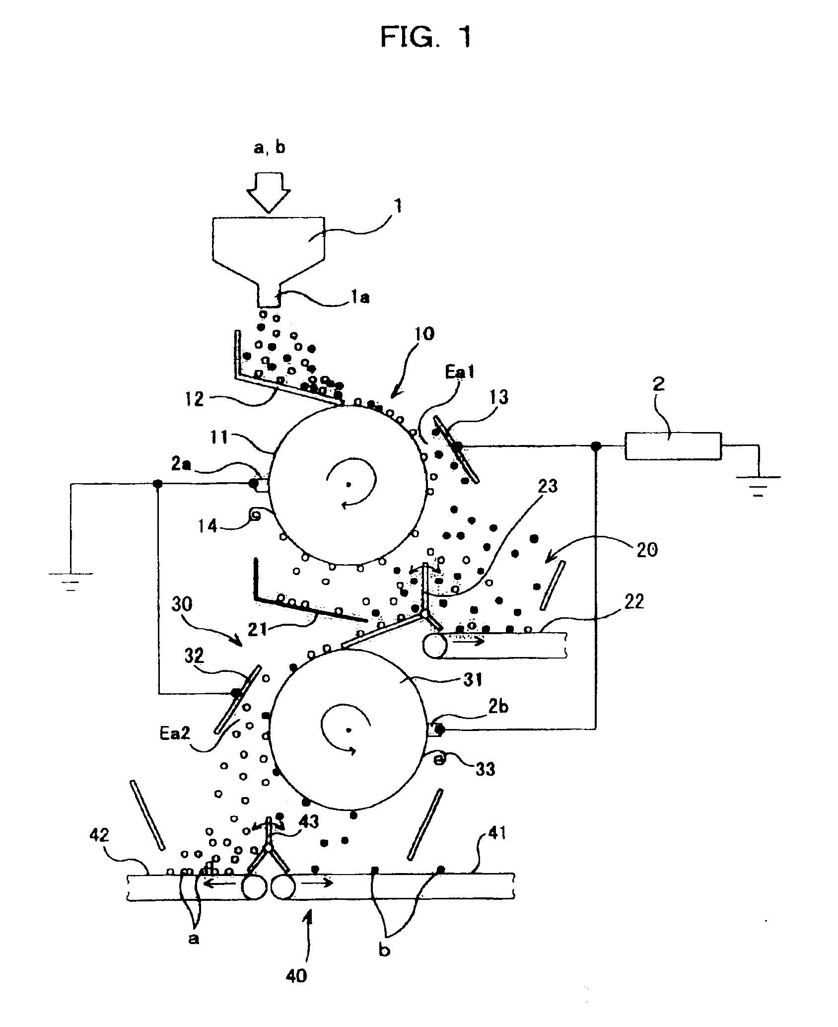
[0028]First, a plastic sorting apparatus according to the present invention will be described with reference to FIGS. 1 and 2.

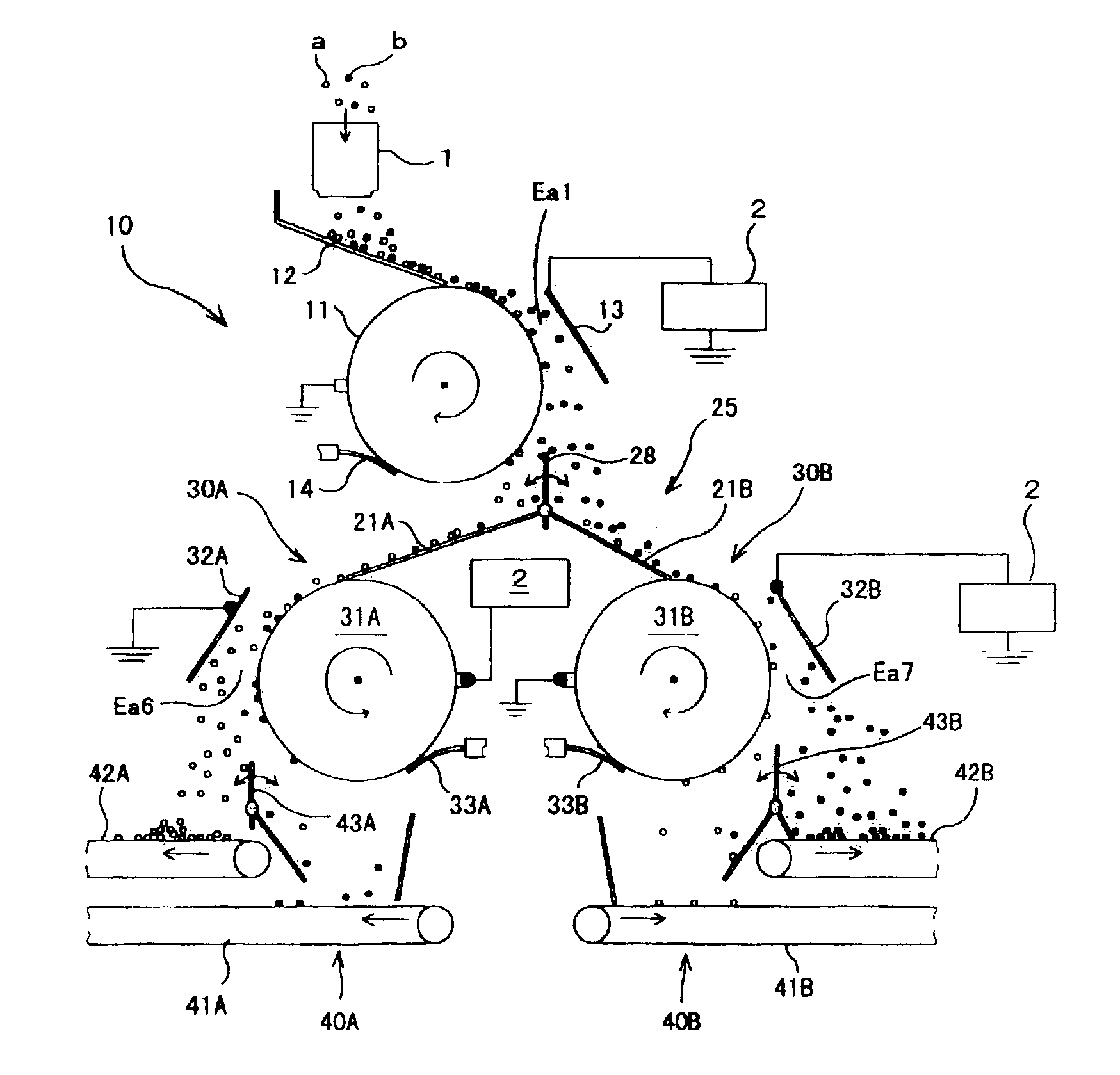
[0029]This plastic sorting apparatus comprises a tribo-electrifying device 1 that stirs at least two different types (materials) of plastic pieces (for example, plastic crushed waste to be sorted out) a and b mixed together to frictionally contact the different types of plastic pieces a and b with each other in order to tribo-electrify the plastic pieces to respective polarities and electrification amounts in accordance with their order in an electrification array, an upper-stage electrostatic separating section 10 arranged below an exit 1a of the tribo-electrifying device 1 to electrostatically separate the plural types of plastic pieces a and b from each other, and a lower-stage electrostatic separating section 30 arranged below the upper-stage electrostatic separating section 10 to further electrostatically separate one of the plural types of plastic piece...

second embodiment

[0047]According to the above described second embodiment, plastic pieces a and b separated toward the lower-stage upper-level opposing electrode 52 in the lower-stage upper-level electrostatic sorting section 50 are fed to the lower-stage lower-level electrostatic separating section 70 via the lower-stage loading chute 61 of the lower-stage connection section 60. At this time, most of the plastic pieces a and b are plastic pieces a separated by the lower-stage upper-level electrostatic separating section 50 of the upper-stage electrostatic separating section 10 and most of which have been electrified to (+). These plastic pieces a are mixed with plastic pieces b slightly electrified to (−). When the plastic pieces a and b are fed to the lower-level lower-stage electrostatic sorting section 70, a large amount of plastic pieces a are separated and collected on the separation and take-out conveyor 42 with a high purity and a high recovery rate, the conveyor 42 being located closer to t...

third embodiment

[0049]Moreover, a plastic sorting apparatus will be described with reference to FIG. 4. The same members as those in the above embodiments are denoted by the same reference numerals, and their description is thus omitted.

[0050]In the first embodiment, plastic pieces a (including a small amount of plastic pieces b) separated toward the upper-stage drum electrode 11 in the upper-stage electrostatic separating section 10 are fed to the lower-stage electrostatic separating section 30 via the upper-stage connection section 20. In this third embodiment, however, plastic pieces b (including a small amount of plastic pieces a) separated toward the upper-stage opposing electrode 13 in the upper-stage electrostatic separating section 10 are fed to the lower-stage electrostatic separating section 90 via the upper-stage connection section 80.

[0051]The upper stage connection section 80 comprises an upper-stage loading chute 81 that receives and feeds plastic pieces a and b separated toward the u...


PUM

PropertyMeasurementUnit
Polarityaaaaaaaaaa
Electrostatic fieldaaaaaaaaaa

Abstract

A first and second electrostatic sorting sections are arranged below a tribo-electrifying device in this order in a vertical direction to form a sorting electrostatic field between a drum electrode and an opposing electrode. Plastic pieces separated from the other plastic pieces by the sorting electrostatic field in the first electrostatic separating section are introduced into a sorting electrostatic field in the second electrostatic separating section for second separation, thereby increasing the separation purity and recovery rate of plastic pieces.

Description

TECHNICAL FIELD[0001]The present invention relates to a plastic sorting apparatus for sorting crushed plastic pieces composed of plural types of plastics, according to their types.BACKGROUND ART[0002]A conventional plastic sorting apparatus comprises two electrode plates arranged parallel with each other in a vertical direction so as to form a space of a predetermined size therebetween, the electrode plates having a high-voltage power supply connected thereto to form a separating electrostatic field therebetween, wherein plastic pieces are loaded into the separating electrostatic field from above, and the electrostatic force of the separating electrostatic field is used to vary the falling trajectories of the plastic pieces correspondingly to the charges of the plastic pieces, thereby separating the plastic pieces from one another according to their type.[0003]However, to improve the separation precision of the conventional apparatuses, it is necessary to use long electrode plates t...

Claims


Application Information

Patent Timeline
IPC IPC(8): B03C7/00B03C7/10B03C7/06B29B17/02
CPCB03C7/006B03C7/06B03C7/10B29B17/02B29B2017/0203B29K2067/00B29K2023/06B29K2023/12B29K2027/06B29K2033/12B29B2017/0265Y02W30/52Y02W30/62B03C7/02
Inventor DAIKU, HIROYUKITSUKAHARA, MASANORIINOUE, TETSUYAMAEHATA, HIDEHIKO
Owner HITACHI ZOSEN CORP
Why Eureka
Try Eureka