Multi-branch planar antennas having multiple resonant frequency bands and wireless terminals incorporating the same

a technology of resonant frequency bands and antennas, applied in the field of communication, can solve the problems of increasing production costs, bandwidth degradation at low-band elements,

Inactive Publication Date: 2005-06-07
SONY CORP
View PDF15 Cites 92 Cited by
  • Summary
  • Abstract
  • Description
  • Claims
  • Application Information

AI Technical Summary

Problems solved by technology

Unfortunately, the increase in the coupling between the two elements by this configuration may result in degradation in bandwidth at the low-band element.
In addition, the parasitic element may dictate tight manufacturing tolerances for proper operation that may increase production costs.

Method used


Image

  • Multi-branch planar antennas having multiple resonant frequency bands and wireless terminals incorporating the same
  • Multi-branch planar antennas having multiple resonant frequency bands and wireless terminals incorporating the same
  • Multi-branch planar antennas having multiple resonant frequency bands and wireless terminals incorporating the same

Examples


Embodiment Construction

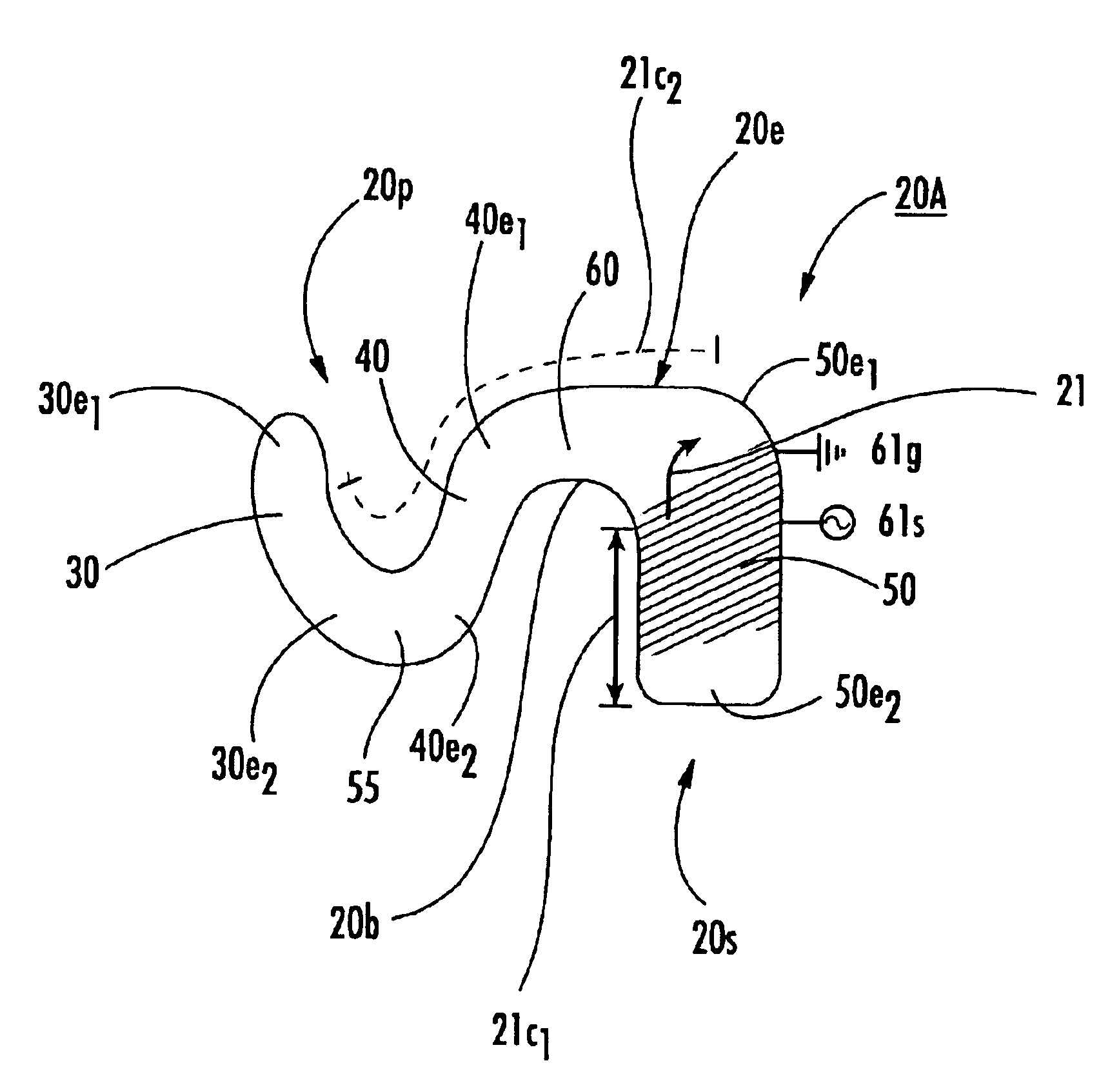
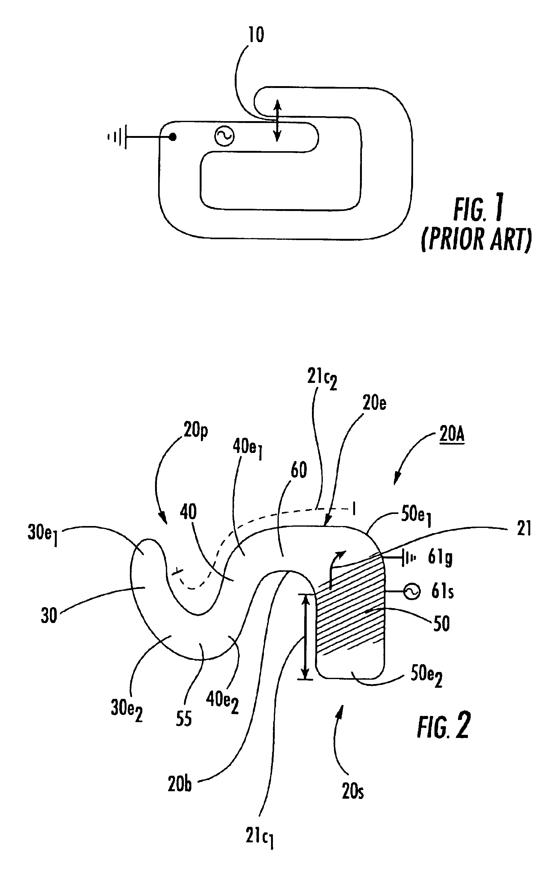
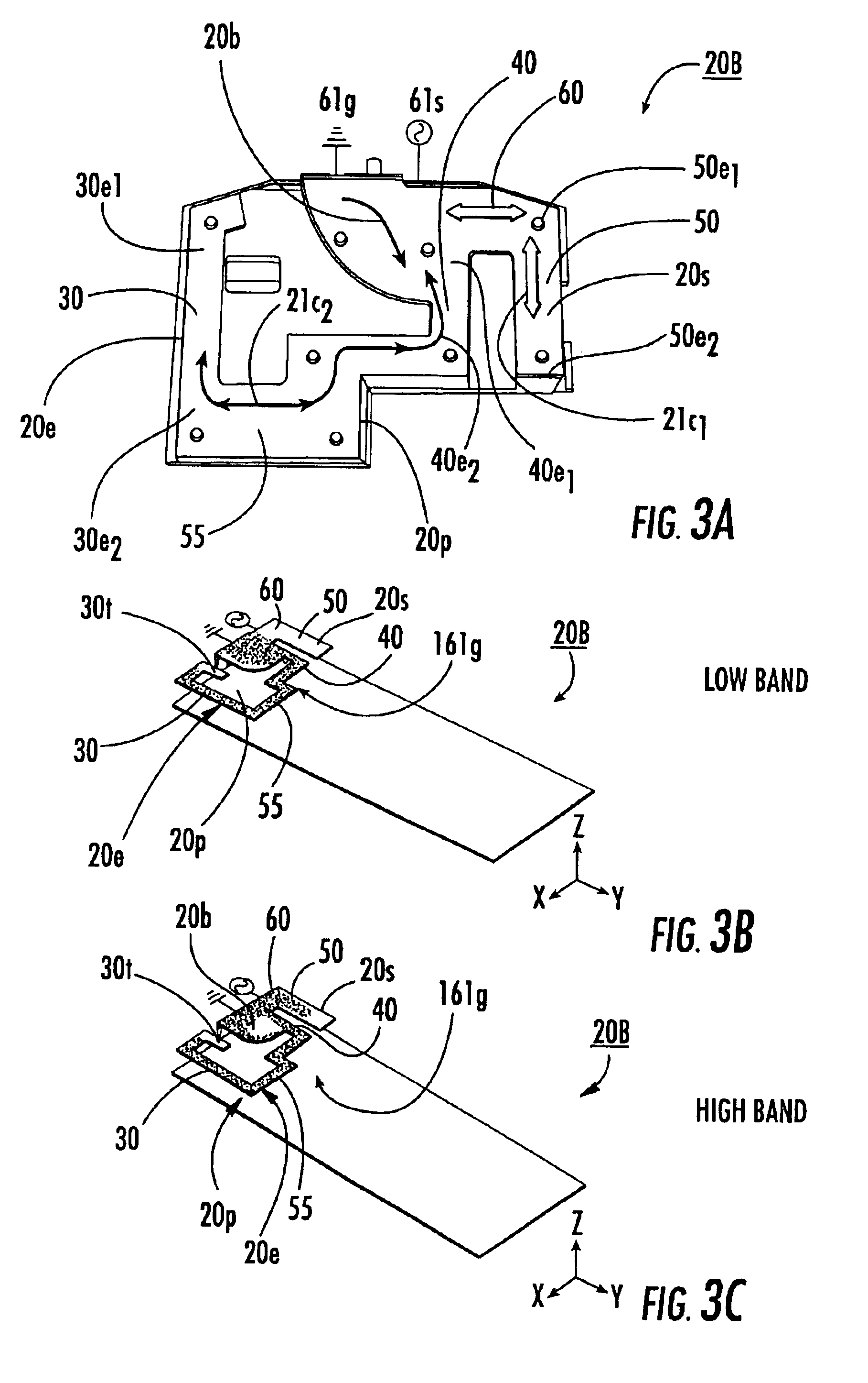
[0037]The present invention will now be described more fully hereinafter with reference to the accompanying drawings, in which embodiments of the invention are shown. This invention may, however, be embodied in many different forms and should not be construed as limited to the embodiments set forth herein; rather, these embodiments are provided so that this disclosure will be thorough and complete, and will fully convey the scope of the invention to those skilled in the art. Like numbers refer to like elements throughout. As used herein, element number 20 generally refers to an antenna and this element number 20 is also used with uppercase alpha suffixes to denote certain embodiments thereof (i.e., 20A, 20B, 20C) for clarity of discussion. Feature 20b (lower case “b”) refers to the bend segment and not a general antenna element embodiment. It will be appreciated that although discussed with respect to a certain antenna embodiment, features or operation of one antenna embodiment can ...


PUM


Abstract

A conductive element with a primary branch and a secondary branch are separated by a bend segment and the signal and ground feeds are positioned adjacent each other on a common portion of the conductive element. The frequencies in the high band may be at least about twice that of the frequencies in the low band. The branches and bend segment are constructed such that the primary branch radiates at both high and low band operation. The two branches combine to form a more efficient high band radiator.

Description

RELATED APPLICATIONS[0001]This application is a continuation-in-part of U.S. patent application Ser. No. 10 / 248,082, filed Dec. 17, 2002, entitled Multi-band, Inverted-F Antenna with Capacitively Created Resonance, and Radio Terminal Using Same, the contents of which are hereby incorporated by reference as if recited in full herein.FIELD OF THE INVENTION[0002]The present invention relates to the field of communications, and, more particularly, to antennas and wireless terminals incorporating the same.BACKGROUND OF THE INVENTION[0003]The size of wireless terminals has been decreasing with many contemporary wireless terminals being less than 11 centimeters in length. Correspondingly, there is increasing interest in small antennas that can be utilized as internally mounted antennas for wireless terminals. Inverted-F antennas, for example, may be well suited for use within the confines of wireless terminals, particularly wireless terminals undergoing miniaturization. Typically, conventi...

Claims


Application Information

Patent Timeline
Patent Type & Authority Patents(United States)
IPC IPC(8): H01Q5/00H01Q9/04H01Q1/24H01Q5/371
CPCH01Q1/243H01Q5/371H01Q9/0442H01Q9/0421
Inventor VANCE, SCOTT LADELLHAYES, GERARDHWANG, HUAN-SHENGSADLER, ROBERT A.
Owner SONY CORP
Why Eureka
Try Eureka