Magnetic disk device with wind shield members

a magnetic disk and wind shield technology, applied in the direction of maintaining head carrier alignment, recording information storage, instruments, etc., to achieve the effect of suppressing the displacement of the magnetic disk

Inactive Publication Date: 2005-06-07
TOSHIBA STORAGE DEVICE CORP
View PDF13 Cites 25 Cited by
  • Summary
  • Abstract
  • Description
  • Claims
  • Application Information

AI Technical Summary

Benefits of technology

[0009]Also, each wind shield member 3 prevents the direct impact of the air flow against the magnetic head arm, and therefore, a surface element opposed to the magnetic recording surface of the magnetic disk is not necessarily required. In the case where opposed surface portions of a predetermined area are formed and placed in proximity to the upper and lower surfaces of the magnetic disk, however, an air bearing structure is formed between the upper and lower surfaces of the magnetic disk and the opposed surface portions, thereby making it possible to suppress displacement of the magnetic disk in the direction of a thickness thereof (a disk fluttering phenomenon).

Problems solved by technology

The external force of the air flow, though low in absolute value, acts as an unforeseeable external disturbance affecting the positioning operation, and therefore is not negligible in the case where the track density is high and a high positioning accuracy is required.

Method used


Image

  • Magnetic disk device with wind shield members
  • Magnetic disk device with wind shield members
  • Magnetic disk device with wind shield members

Examples


Embodiment Construction

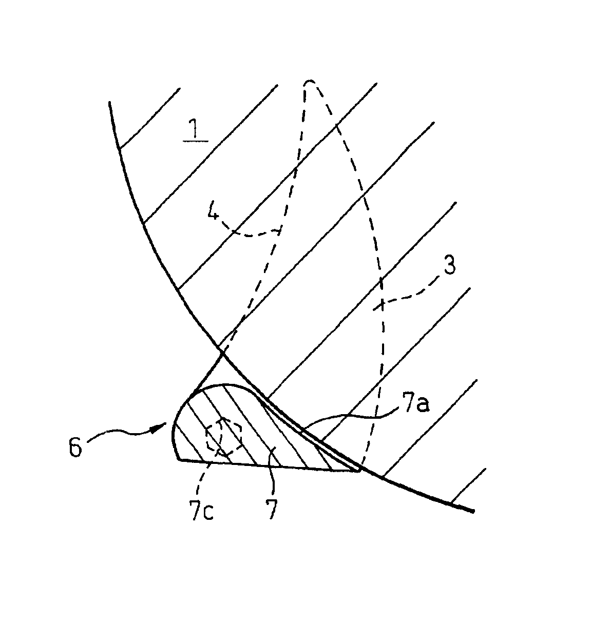
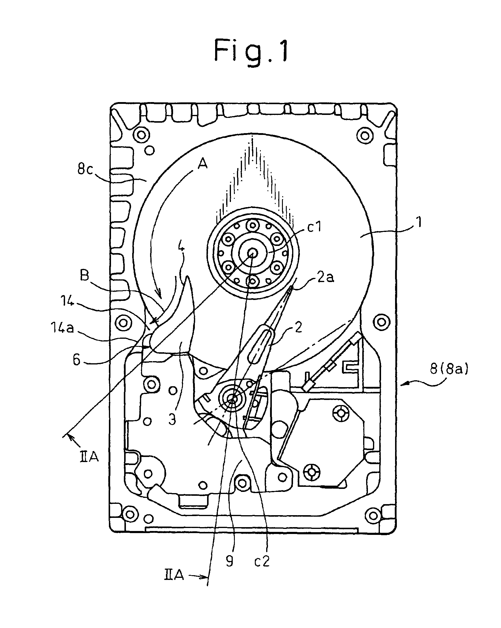
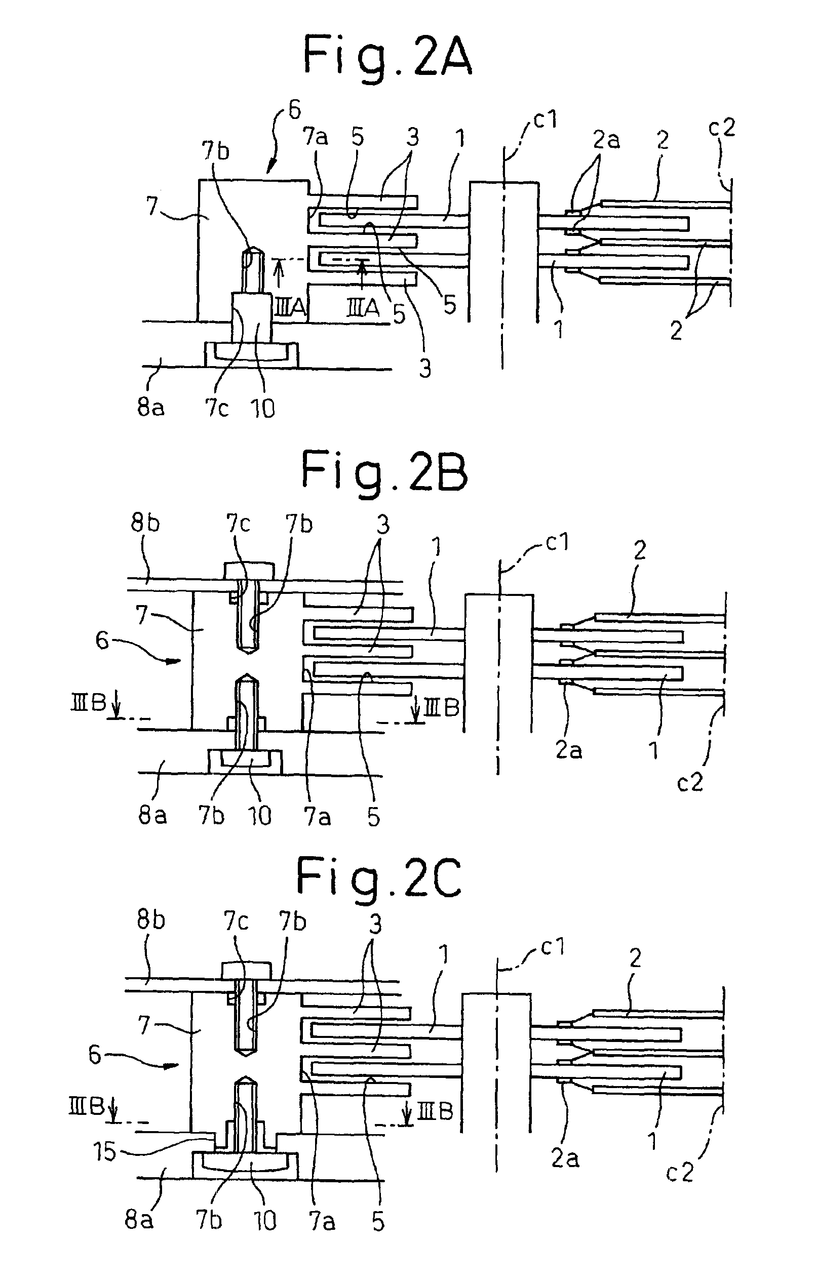
[0024]FIGS. 1 to 3A show a magnetic disk device of an embodiment of the present invention. The magnetic disk device comprises a box-shaped disk case 8 comprising a base body 8a and a cover plate 8b coupled with each other, and magnetic disks 1, magnetic head arms 2 and a wind shield block 6 are hermetically accommodated in the disk case 8. Each magnetic disk 1 has a magnetic recording surface on each of the upper and lower surfaces thereof, and a plurality of the magnetic disks 1 are rotatably arranged about a rotation axis c1. A shroud 8c for surrounding the outer peripheries of the magnetic disks 1 is arranged as near as possible to the outer peripheries of the magnetic disks 1 in the disk case 8, thereby preventing generation of disk fluttering phenomenon which arises due to the air flow between vertically adjacent magnetic disks 1.

[0025]The magnetic head arms 2 are rotationally driven about a rotation axis c2 by a magnetic circuit 9 in such a manner that a magnetic head slider 2...


PUM

PropertyMeasurementUnit
shapeaaaaaaaaaa
thicknessaaaaaaaaaa
dimensionaaaaaaaaaa

Abstract

The magnetic disk device includes magnetic disks, magnetic head arms and wind shield members arranged above and below the magnetic disks, respectively, in a region adjacent to the magnetic head arms. The wind shield members are arranged on the rotationally upstream side of the magnetic head arms, and the air flow generated by the rotation of the magnetic disks and impinging against the magnetic head arms is guided to the outside of the magnetic disks.

Description

BACKGROUND OF THE INVENTION[0001]1. Field of the Invention[0002]The present invention relates to a magnetic disk device with wind shield members.[0003]2. Description of the Related Art[0004]In a magnetic disk device, in general, read and write operations are carried out, with respect to a magnetic disk rotating at a high speed, by a magnetic head floating over the magnetic disk, and a positioning operation of the magnetic head is performed by driving a magnetic head arm carrying the magnetic head at the forward end thereof.[0005]Above the magnetic disk, on the other hand, an air flow is generated, by the high-speed rotation of the magnetic disk, and acts as an external force against the magnetic head or the magnetic head arm. The external force of the air flow, though low in absolute value, acts as an unforeseeable external disturbance affecting the positioning operation, and therefore is not negligible in the case where the track density is high and a high positioning accuracy is r...

Claims


Application Information

Patent Timeline
Patent Type & Authority Patents(United States)
IPC IPC(8): G11B33/14G11B5/60G11B25/04G11B21/21
CPCG11B33/148G11B5/6005G11B5/40G11B21/21
Inventor SAKATA, MASAHARUINO, TSUNEYORIYOSHIDA, MITSUAKINAGAMORI, TOMOHIRO
Owner TOSHIBA STORAGE DEVICE CORP
Why Eureka
Try Eureka