Cache memory for identifying locked and least recently used storage locations

a storage location and cache memory technology, applied in the field of cache memory for identifying locked and least recently used storage locations, can solve the problems of limiting the amount of control information that may be carried therein, and the cost of a lock bit can be significant, so as to eliminate the recording of usage information and save memory.

Inactive Publication Date: 2005-06-07
RPX CORP +1
View PDF8 Cites 12 Cited by
  • Summary
  • Abstract
  • Description
  • Claims
  • Application Information

AI Technical Summary

Benefits of technology

[0003]From the foregoing, it may be appreciated by those skilled in the art that a need has arisen to combine control functions and information in a fewer number of bits of the tag information in a cache line of a cache memory. In accordance with the present invention, a cache memory for identifying locked and least recently used storage locations is provided that substantially eliminates or greatly reduces disadvantages and problems associated with conventional cache memory designs.

Problems solved by technology

The number of fields and bits for control is relatively small and may limit the amount of control information that may be carried therein.
Since every data entry needs a lock bit, the cost of a lock bit can be significant with large cache sizes.

Method used


Image

  • Cache memory for identifying locked and least recently used storage locations
  • Cache memory for identifying locked and least recently used storage locations
  • Cache memory for identifying locked and least recently used storage locations

Examples


Embodiment Construction

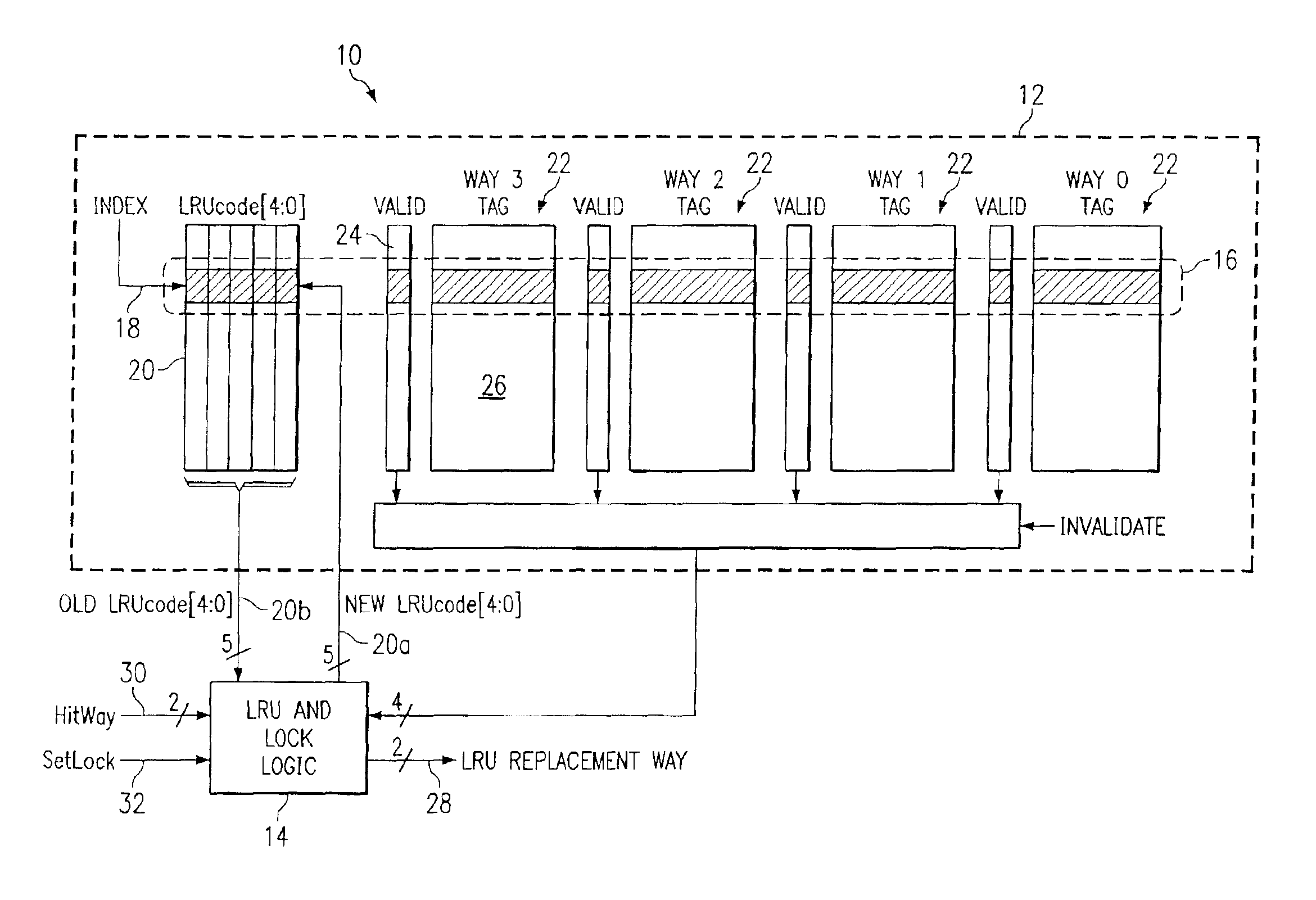
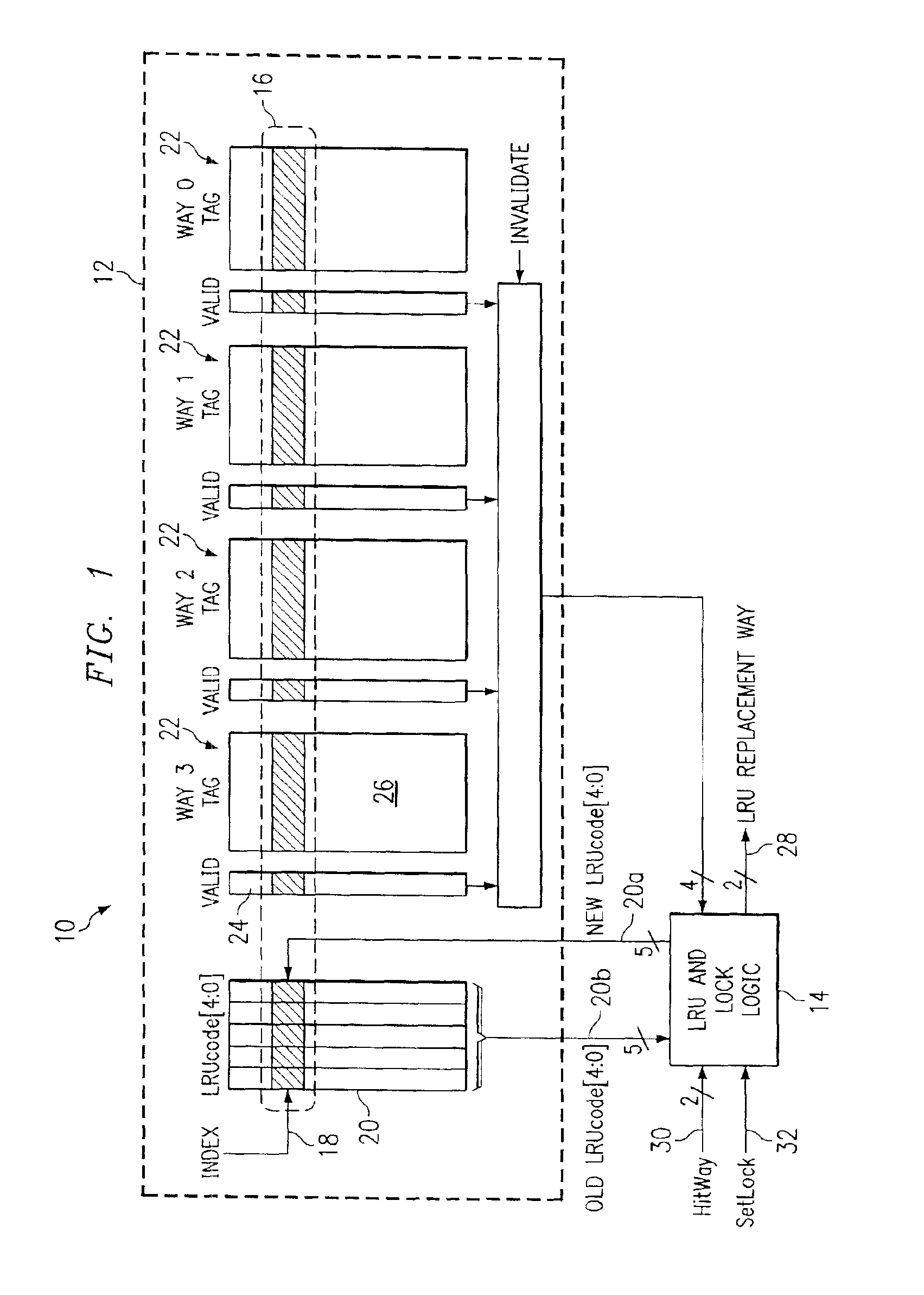
[0011]FIG. 1 is a block diagram of a cache memory 10. For purposes of illustration, cache memory 10 will be discussed as a four way set associative though the present invention may be applicable to any number of ways for a set associative cache. Cache memory 10 includes a memory unit 12 and a logic block 14. Memory unit 12 is divided into a number of storage locations or sets 16 with each set accessed by an index 18. Each set has a priority lock code 20 in a code memory block and four data memory blocks or ways 22 associated therewith. Priority lock code 20 determines which way 22 associated with index 18 has been most recently used (MRU), least recently used (LRU), next most recently used (MRU-1), and next least recently used (LRU-1). Priority lock code 20 also determines which way 22 is in a locked state. When a way 22 is locked, its set information cannot be replaced until the set information is invalidated. Each way 22 includes a valid bit 24 and tag information 26 for each set ...


PUM


Abstract

A cache memory includes a plurality of data memory blocks and a code memory block. Each data memory block has a plurality of storage locations and has a particular storage location identified by a same index value. The code memory block has a plurality of code values with a particular code value being associated with the same index value. The particular code value is operable to identify which ones of the particular storage locations associated with the same index value are locked to prevent alteration of contents therein. The particular code value is also operable to identify which particular storage location has been most recently used and which particular storage location has been least recently used of the particular storage locations associated with the same index value.

Description

TECHNICAL FIELD OF THE INVENTION[0001]The present invention relates in general to memory processing techniques and more particularly to a cache memory for identifying locked and least recently used storage locations.BACKGROUND OF THE INVENTION[0002]A cache memory typically stores data that is more frequently used for fast access in order to avoid the delay of retrieving data from a main memory. The data is stored in the cache memory in one or more storage locations known as lines. Each line includes the data and tag information identifying what data is stored in the line. The tag information includes an address field and various control fields and bits. The number of fields and bits for control is relatively small and may limit the amount of control information that may be carried therein. Real time performance of a cache can be improved by setting a lock bit associated with a cache line so that the cache line data cannot be evicted from the cache for being least recently used. Sinc...

Claims


Application Information

Patent Timeline
Patent Type & Authority Patents(United States)
IPC IPC(8): G06F12/12
CPCG06F12/126G06F12/125
Inventor ZHANG, DAVID X.YEAGER, KENNETH C.
Owner RPX CORP
Why Eureka
Try Eureka