Flexible element

Inactive Publication Date: 2005-06-14
CONTINENTAL AUTOMOTIVE GMBH
View PDF12 Cites 2 Cited by
  • Summary
  • Abstract
  • Description
  • Claims
  • Application Information

AI Technical Summary

Benefits of technology

[0003]The object of the present invention is to provide a flexible element which is able to compensate for the different linear expansions of the sheathing and core in the event of changes in temperature.
[0005]In this case, the flexible element according to the invention affords the advantage that the linear compensation can take place solely between the sleeve elements and the tube, which is Particularly advantageous when, as is frequently provided in the case of flexible shafts, for example, the sleeve elements can be fixed in housings or mountings on the drive side and power takeoff side.
[0007]A slight radial play is preferably provided between the tubular sheathing and the sleeve element, so that the linear compensation can take place with just a small amount of friction, but at the same time, there is also a certain amount of protection against the ingress of dirt.
[0010]Since, in the case of movable sleeve elements, there has to be the risk under some circumstances of the tube ends slipping out of the sleeve elements or else of the core falling out of the protective sheathing prior to the final installation, it is provided, in a further, preferred design of the invention, that at at least one end, preferably at both ends, of the flexible element, there is fixed on the core a ring element which forms an axial stop for the associated sleeve element which encloses it and is movable axially. In the case of ring elements provided on two sides, there is no longer any risk of falling apart, even if handled carelessly, and so this design is preferred, in which case a further advantage is that the flexible element is constructed symmetrically, with the result that it cannot be fitted inverted.

Problems solved by technology

In the case of flexible elements, for example pliant flexible shafts or Bowden cables, in which the forces or moments can be transmitted by the core, or else in the case of electric lines, there is a fundamental problem of the protecting sheathings, which generally consist of plastic, having a considerably different coefficient of thermal expansion in comparison with the core which consists, for example, of steel or another metal on account of the mechanical stress or in order to achieve electric conductivity.
The sleeves have previously been bonded or welded to the tube, with the result that when the sleeves are fixed axially and the core is fixed axially, problems may occur because of the different expansions due to temperature.
This results in distortions of the flexible element, which may, for example in the case of drive elements, ensure that the element moves from its originally designated position, but at least cause frictional losses and an increased wear due to the bearing forces between the tubular sheathing and core.

Method used


Image

  • Flexible element
  • Flexible element

Examples


Embodiment Construction

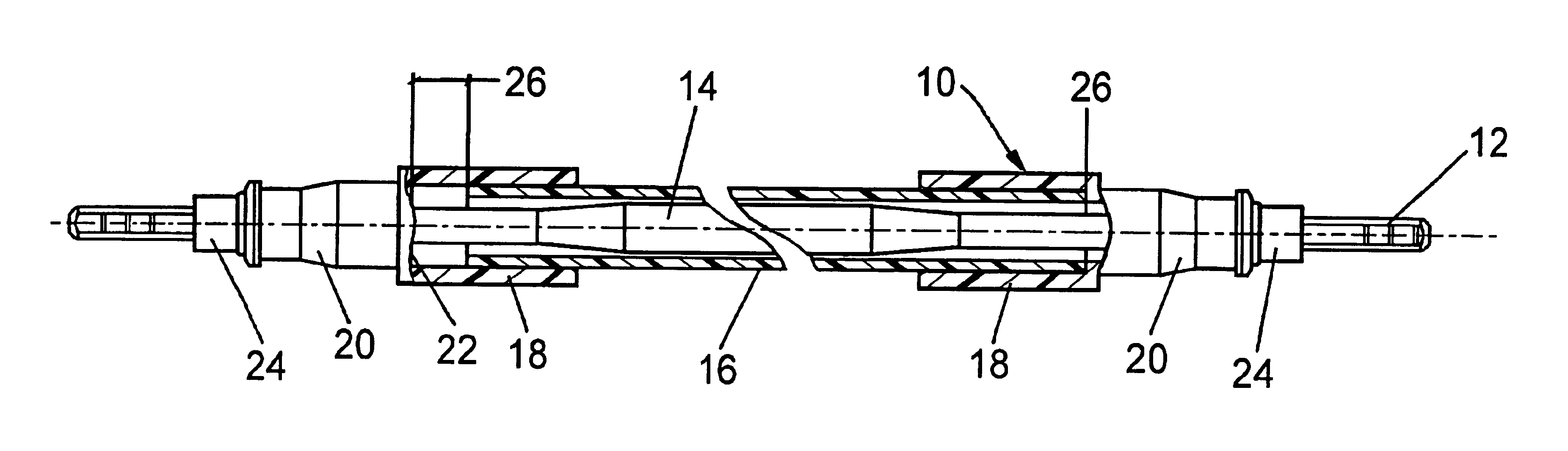
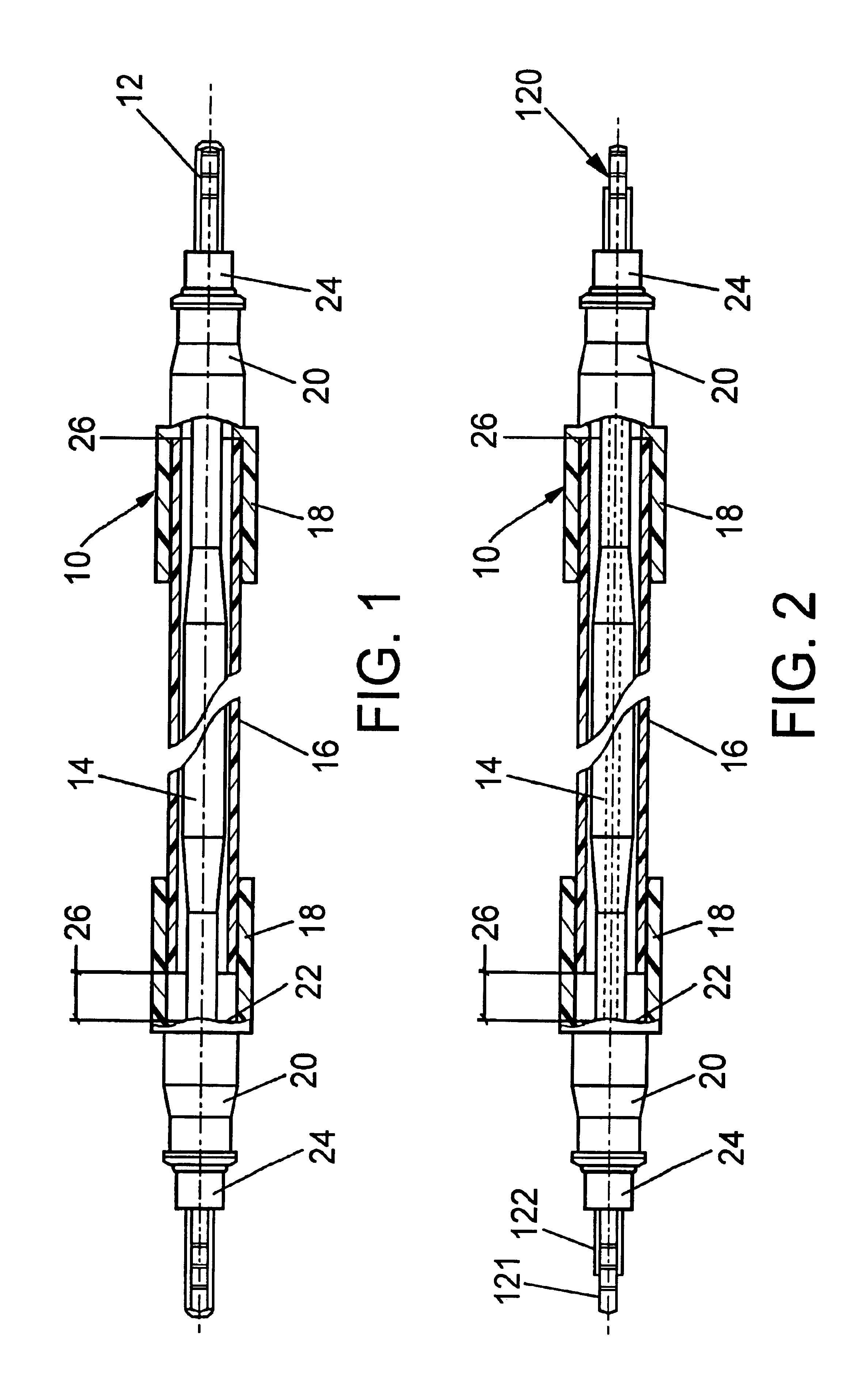
[0014]FIG. 1 presents a partially cut-open illustration of a flexible drive shaft 10 as provided in the automotive sector for the connection between an electric drive motor and an electric of ventilator window actuated by the latter. For the transmission of the necessary moment, the flexible drive shaft has a steel core of customary design with a thickened central section 14. For the protection of the shaft core 12 and also of the surrounding parts, the core is surrounded by a flexible tubular sheathing 16 which sits at both of its ends in hollow cylindrical sections 18 of sleeve elements 20. In this case, the tube ends are not connected fixedly to the hollow cylindrical sections 18; rather, they only sit in the latter with slight play, with the result that an axial displacement of the tube relative to the sleeve elements 20 is possible until the tube ends bear against end surfaces 22.

[0015]The sleeve elements, which preferably consist of plastic, can be fixed on the drive side and ...


PUM


Abstract

A flexible element, for example a flexible shaft, has a core (12) and a tubular sheathing (16) protecting the latter. Sleeve elements (20) surround the core and hold the tubular sheathing (16) between them. Different co-efficients of thermal expansion of the material for the tubular sheathing in comparison to the material of the core have previously led to undesirable distortions. To avoid these distortions in a structurally simple manner, at least one sleeve element (20) holds the tubular sheathing (16) with limited axial play (26). The play compensation between the sleeve element (20) and tubular sheathing (16) is particularly advantageous when the sleeve elements (20) are used for fixing the flexible elements (10).

Description

FIELD AND BACKGROUND OF THE INVENTION[0001]The invention is concerned with a flexible element having a core and a tubular sheathing protecting the latter, and sleeve elements which surround the core and between which the tubular sheathing is held, the core and the tubular sheathing having different coefficients of thermal expansion.[0002]In the case of flexible elements, for example pliant flexible shafts or Bowden cables, in which the forces or moments can be transmitted by the core, or else in the case of electric lines, there is a fundamental problem of the protecting sheathings, which generally consist of plastic, having a considerably different coefficient of thermal expansion in comparison with the core which consists, for example, of steel or another metal on account of the mechanical stress or in order to achieve electric conductivity. The sleeves have previously been bonded or welded to the tube, with the result that when the sleeves are fixed axially and the core is fixed ...

Claims


Application Information

Patent Timeline
IPC IPC(8): F16C1/00F16C1/22F16C1/26F16C1/10
CPCF16C1/226F16C1/06F16C1/262Y10T74/20462
Inventor DECKER, MARKUSPFEIFFER, STEFANEMMEL, LARS
Owner CONTINENTAL AUTOMOTIVE GMBH
Why Eureka
Try Eureka