Speed change mechanism of automatic transmission

a technology of automatic transmission and transmission mechanism, which is applied in the direction of gearing details, gearing, transportation and packaging, etc., can solve the problems of poor fuel consumption and drivability of the vehicle, and poor fuel consumption and drivability so as to achieve sufficient freedom in selecting gear ratio and improve drivability and fuel consumption of the associated motor vehicle.

Inactive Publication Date: 2005-06-14
JATCO LTD
View PDF9 Cites 21 Cited by
  • Summary
  • Abstract
  • Description
  • Claims
  • Application Information

AI Technical Summary

Benefits of technology

[0012]In view of the above-mentioned various facts in conventional technique, the present invention aims to provide a speed change mechanism of an automatic transmission, in which input and output shafts are arranged coaxially for achieving a compact construction of the mechanism, a freedom in selecting gear ratio is sufficiently obtained and drivability and fuel consumption of an associated motor vehicle are improved.

Problems solved by technology

Furthermore, if the ratio coverage fails to have a satisfied maximum value, fuel consumption and drivability of an associated motor vehicle become poor.
Furthermore, if the “1-R ratio” fails to be set at a desired value, that is, for example, if the “1-R ratio” is set at a smaller value, drivability of the vehicle becomes poor because respective output torques produced at 1st forward speed and reverse position are largely different.
In this case, fuel consumption and drivability of the vehicle become poor.

Method used


Image

  • Speed change mechanism of automatic transmission
  • Speed change mechanism of automatic transmission
  • Speed change mechanism of automatic transmission

Examples


Embodiment Construction

[0026]In the following, an embodiment of the present invention will be described in detail with reference to the accompanying drawings.

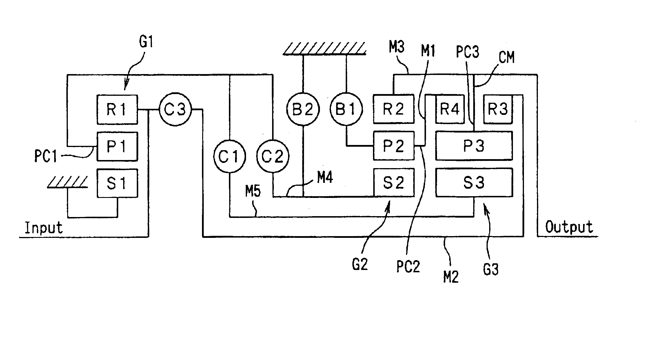
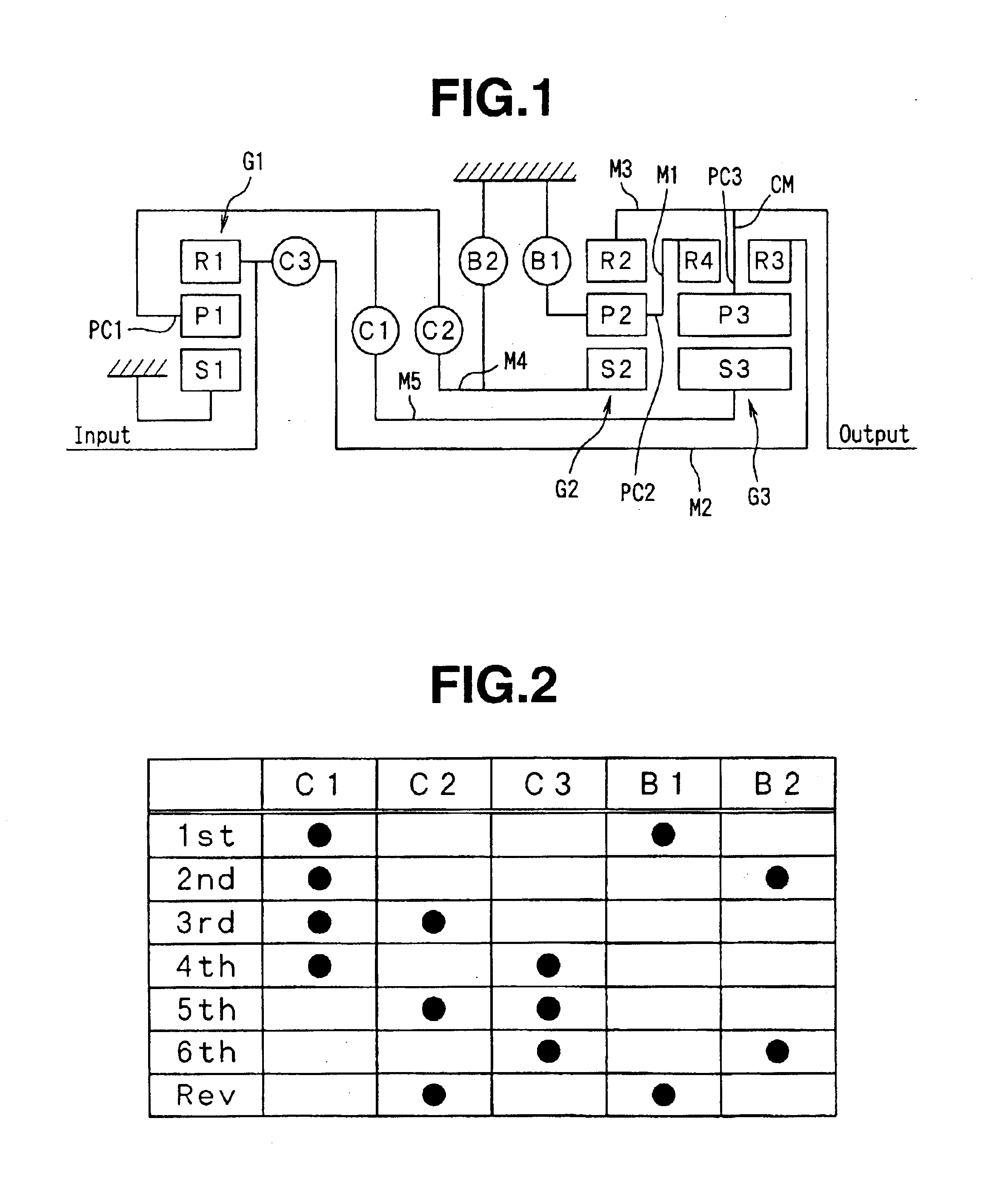
[0027]FIG. 1 shows schematically a speed change mechanism of an automatic transmission, which is the embodiment of the present invention.

[0028]In the drawing, denoted by “Input” is an input shaft into which a torque is applied from an engine (not shown) through a torque converter (not shown), and denoted by “Output” is an output shaft from which a torque is led to driven road wheels (not shown) of an associated motor vehicle through a final gear (not shown). These input and output shafts are arranged coaxially, as shown.

[0029]In the side of the input shaft “Input”, there is arranged a first planetary gear unit G1 which converts an input rotation from the input shaft “Input” to an output rotation whose speed is lower than that of the input rotation. While, in the side of the output shaft “Output”, there are arranged a second planetary gear unit G2 and...


PUM


Abstract

A first planetary gear unit is arranged to convert an input rotation from an input shaft to an output rotation whose speed is lower than that of the input rotation. A first unit including second and third planetary gear units is arranged between the first planetary gear unit and the output shaft. The first unit manages the first planetary gear unit's output rotation and provides the output shaft with seven types of rotation which correspond to 6-forward speed and one reverse positions. A second unit is arranged between the first planetary gear unit and the first unit to manage a power transmission therebetween. One of the second and third planetary gear units is of a double ring type, each being meshed with the sun gear and inside and outside ring gears, and a pinion carrier carrying the pinions. The pinion carrier is connected to the output shaft to rotate therewith.

Description

BACKGROUND OF THE INVENTION[0001]1. Field of the Invention[0002]The present invention relates in general to automatic transmissions for wheeled motor vehicles, and more particularly to a speed change mechanism of the automatic transmissions, which has 6-forward speed and one reverse positions.[0003]2. Field of the Related Art[0004]One of the speed change mechanisms of the above-mentioned type is shown in FIG. 5 of Japanese Laid-open Patent Application (Tokkaihei) 4-219553. The speed change mechanism of this published application comprises generally an input shaft, a planetary gear train including a single pinion type gear unit and two single pinion type gear units, three clutches, two brakes and an output shaft. For achieving 6-forward speed and one reverse portions, the three clutches and two brakes are selectively engaged and disengaged in a given manner.[0005]To provide the speed change mechanism with an overdrive speed position, it is necessary to apply an input force to a pinio...

Claims


Application Information

Patent Timeline
Patent Type & Authority Patents(United States)
IPC IPC(8): F16H3/66F16H3/44
CPCF16H3/663F16H2200/0052F16H2200/2097F16H2200/2043F16H2200/201F16H3/62
Inventor SUGIHARA, TSUYOSHIYAMAGUCHI, TOSHIOOGURI, KAZUO
Owner JATCO LTD
Why Eureka
Try Eureka