Permanent magnet motor

a permanent magnet, rotor type technology, applied in the direction of magnetic circuit rotating parts, dynamo-electric machines, magnetic circuit shape/form/construction, etc., can solve the problems of reducing the energy density of the motor, speed, higher-torque motors, and unavoidable leakage of magnetic flux to the outer peripheral rib portions, so as to reduce the leakage flux

Inactive Publication Date: 2005-06-14
TEIJIN SEIKI CO LTD
View PDF12 Cites 53 Cited by
  • Summary
  • Abstract
  • Description
  • Claims
  • Application Information

AI Technical Summary

Benefits of technology

[0010]The invention has been devised to over come the above-described problems, and its object is to provide a permanent magnet motor which ma

Problems solved by technology

The embedded magnet-type motor realizes a high torque since permanent magnets are effectively arranged in the core to provide saliency in a magnetic circuit in the rotor, but it has been thought that the leakage of the magnetic flux to outer peripheral rib portions is unavoidable for the reason of mechanical strength.
The abov

Method used


Image

  • Permanent magnet motor
  • Permanent magnet motor
  • Permanent magnet motor

Examples


first embodiment

[First Embodiment]

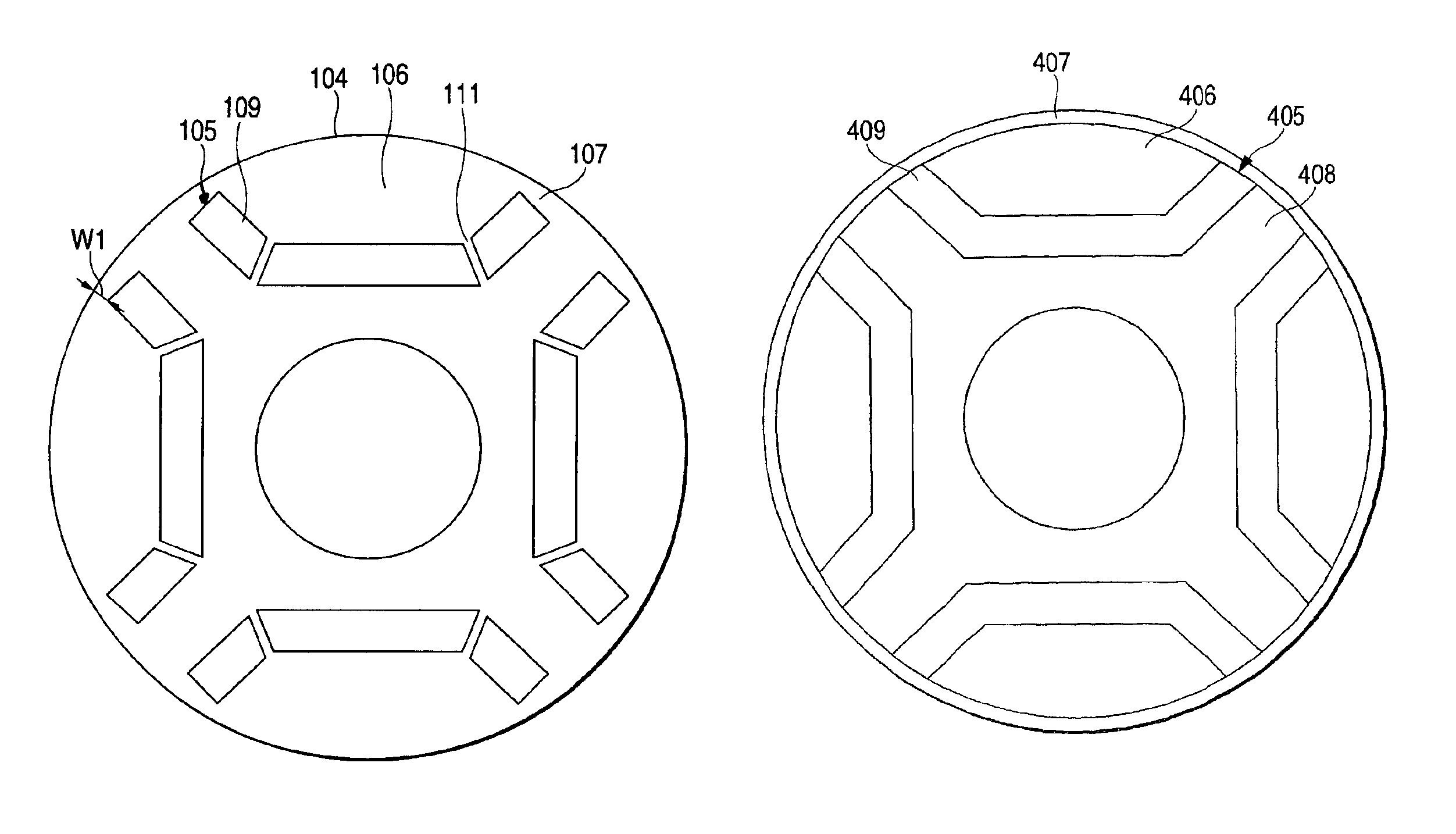
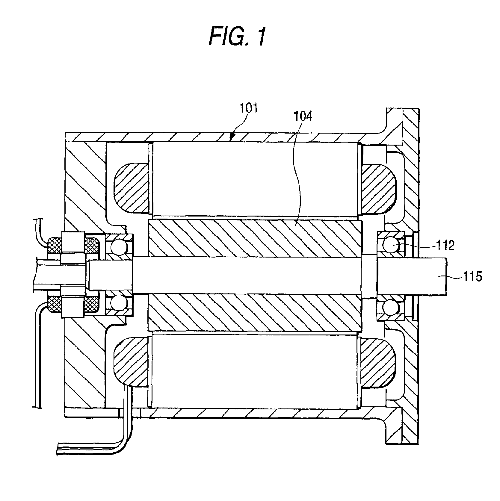
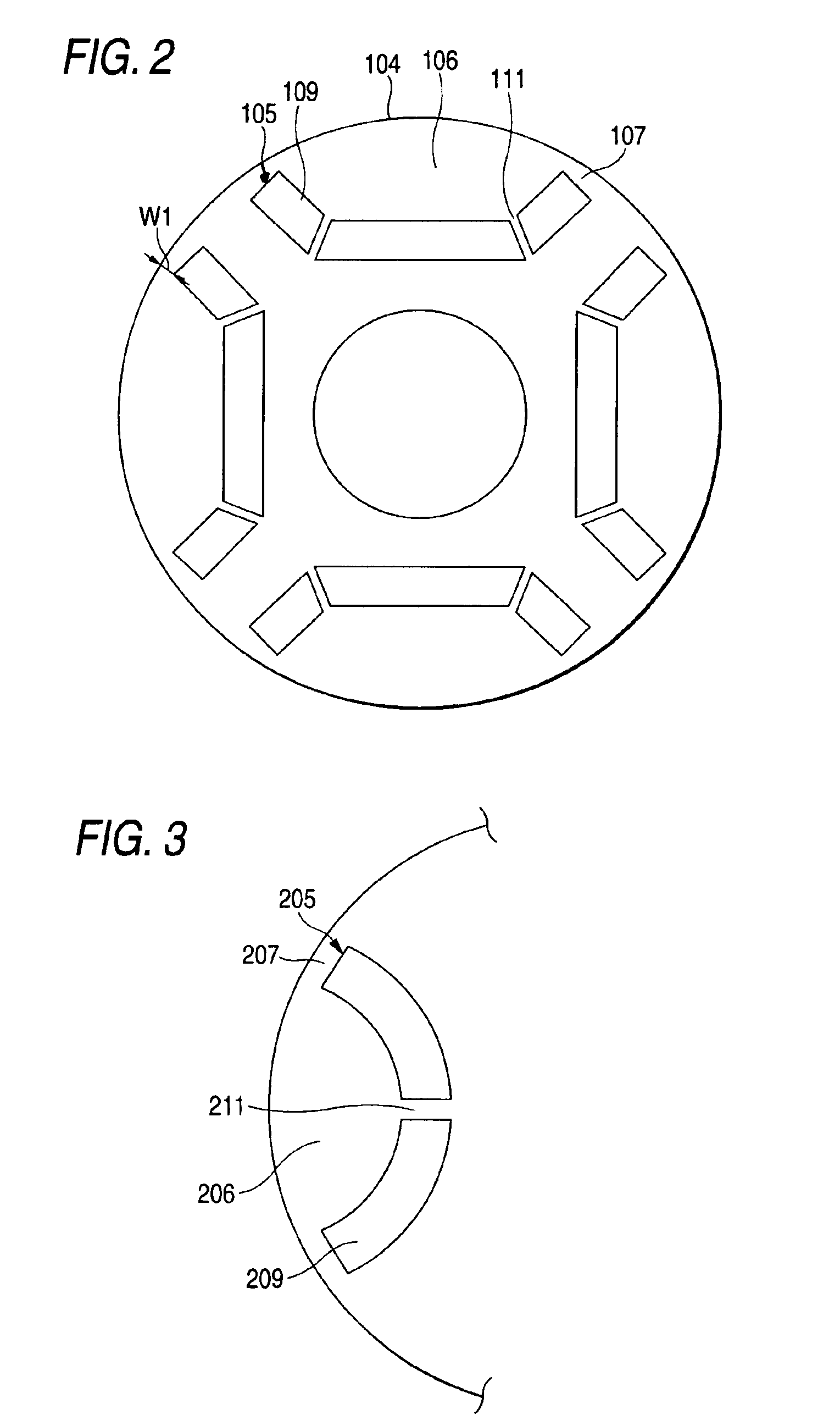
[0026]FIG. 1 is a sectional view illustrating a permanent magnet motor in accordance with a first embodiment of the invention. FIG. 2 is a cross-sectional view of a rotor core shown in FIG. 1. In FIG. 1, a rotor core 104 is disposed inside a stator core 101, and a motor output shaft 115, which rotates with the rotor core at the central axis of rotation of the rotor core, is fixed to the stator core by means of a bearing 112. In FIGS. 1 and 2, reference numeral 104 denotes the rotor core which is formed in a cylindrical shape by a single steel member or by laminating a multiplicity of punched steel plates. The rotor core 104 has a plurality of open trapezoidal shaped magnet insertion holes 105, and is provided with permanent magnets 109 which are inserted in the magnet insertion holes 105. Numeral 111 denotes a rib portion which prevents the centrifugal force acting in the permanent magnets 109 and a magnetic-flux holding portion 106 from being concentrated in an ou...

second embodiment

[Second Embodiment]

[0031]As shown in FIG. 3, the invention is also applicable to a U-shaped permanent magnet-embedded type rotor as another form in which the rib portions are provided. As shown in FIG. 3, the U-shaped magnet is divided into two parts, which are inserted in magnet embedding grooves 205 of the rotor. As the permanent magnet is thus divided into two parts by providing a rib portion 211, there is an advantage in that the load due to the centrifugal force of permanent magnets 209 and a magnetic-flux holding portion 206 is prevented from being concentrated in a rotor connecting portion 207. As a result, advantages similar to those of the first embodiment can be offered.

third embodiment

[Third Embodiment]

[0032]As shown in FIG. 4, there is a V-shaped permanent magnet-embedded rotor as still another embodiment. As shown in FIG. 4, the V-shaped permanent magnet is divided into two parts, which are inserted in magnet embedding grooves 305 of the rotor. As the permanent magnet is thus divided into two parts by providing a rib portion 311, there is an advantage in that the load due to the centrifugal force of permanent magnets 309 and a magnetic-flux holding portion 306 is prevented from being concentrated in a rotor connecting portion 307 in the same way as the rotor using the U-shaped permanent magnets. As a result, advantages similar to those of the open trapezoidal shaped permanent magnet-embedded rotor in accordance with the first embodiment can be offered.

[0033]The forms of the permanent magnets are not limited to the open trapezoidal shaped, open U-shaped, and V-shaped forms of the above-described first, second, and third embodiments, it is possible to obtain simi...


PUM


Abstract

Each permanent magnet formed in an open-letter shape is divided into a plurality of parts, the divided magnets are respectively fitted in open letter-shaped inserting portions, and ribs are respectively provided in dividing portions of the permanent magnets. Accordingly, it is possible to prevent the breakage of pole connecting portions at an outermost periphery of the rotor as adjacent inner peripheral-side permanent magnets directly come into contact with and push the outer peripheral-side permanent magnets. Alternatively, an annular nonmagnetic material is provided on an outer peripheral portion of the rotor so as to cover the open letter-shaped permanent magnets and magnetic material portions inside the open-letter portions, whereby the rotor core is made resistant against breakage, and the flux leakage is minimized.

Description

BACKGROUND OF THE INVENTION[0001]The present invention relates to a permanent magnet-embedded rotor-type motor.[0002]In recent years, various motors have come to be developed, but the application of permanent magnet motors has been carried out extensively because of the high energy density and efficiency. Further, the development of embedded magnet-type motors, in which permanent magnets arranged in a rotor are embedded in a core, is underway. The embedded magnet-type motor realizes a high torque since permanent magnets are effectively arranged in the core to provide saliency in a magnetic circuit in the rotor, but it has been thought that the leakage of the magnetic flux to outer peripheral rib portions is unavoidable for the reason of mechanical strength. The outer peripheral ribs must be made thin to reduce the leakage of the magnetic flux. On the other hand, however, to effect high-speed rotation, it is necessary to secure mechanical strength by making the outer peripheral ribs ...

Claims


Application Information

Patent Timeline
IPC IPC(8): H02K1/27H02K1/22H02K21/16
CPCH02K1/2766
Inventor HATTORI, MASAKAZUMAKINO, NAOHIRO
Owner TEIJIN SEIKI CO LTD
Why Eureka
Try Eureka