Shadow mask for cathode ray tube

Inactive Publication Date: 2005-06-14
SAMSUNG SDI CO LTD
View PDF3 Cites 0 Cited by
  • Summary
  • Abstract
  • Description
  • Claims
  • Application Information

AI Technical Summary

Benefits of technology

[0012]In one embodiment, the present invention is a shadow mask for a cathode ray tube that has an optimal radius of curvature for minimizing the effect of receiving an external sho

Problems solved by technology

However, the shadow mask becomes structurally weak if it is made to a large size and having a large radius of curvature, leading to various problems.
For example, if a radius of curvature of the shadow mask is made to 1.6R, the shadow mask is unable to easily maintain its shape in the event the shadow mask receives a certain level of shock.
Such deformation of the shadow mask greatly reduces the quality of the CRT.
Further, when the shadow mask is large and has a flattened curvature, the shadow mask becomes susceptible to howling.
With the increased size of the shadow mask, it becomes structurally weak as described above such that

Method used


Image

  • Shadow mask for cathode ray tube
  • Shadow mask for cathode ray tube
  • Shadow mask for cathode ray tube

Examples


Example

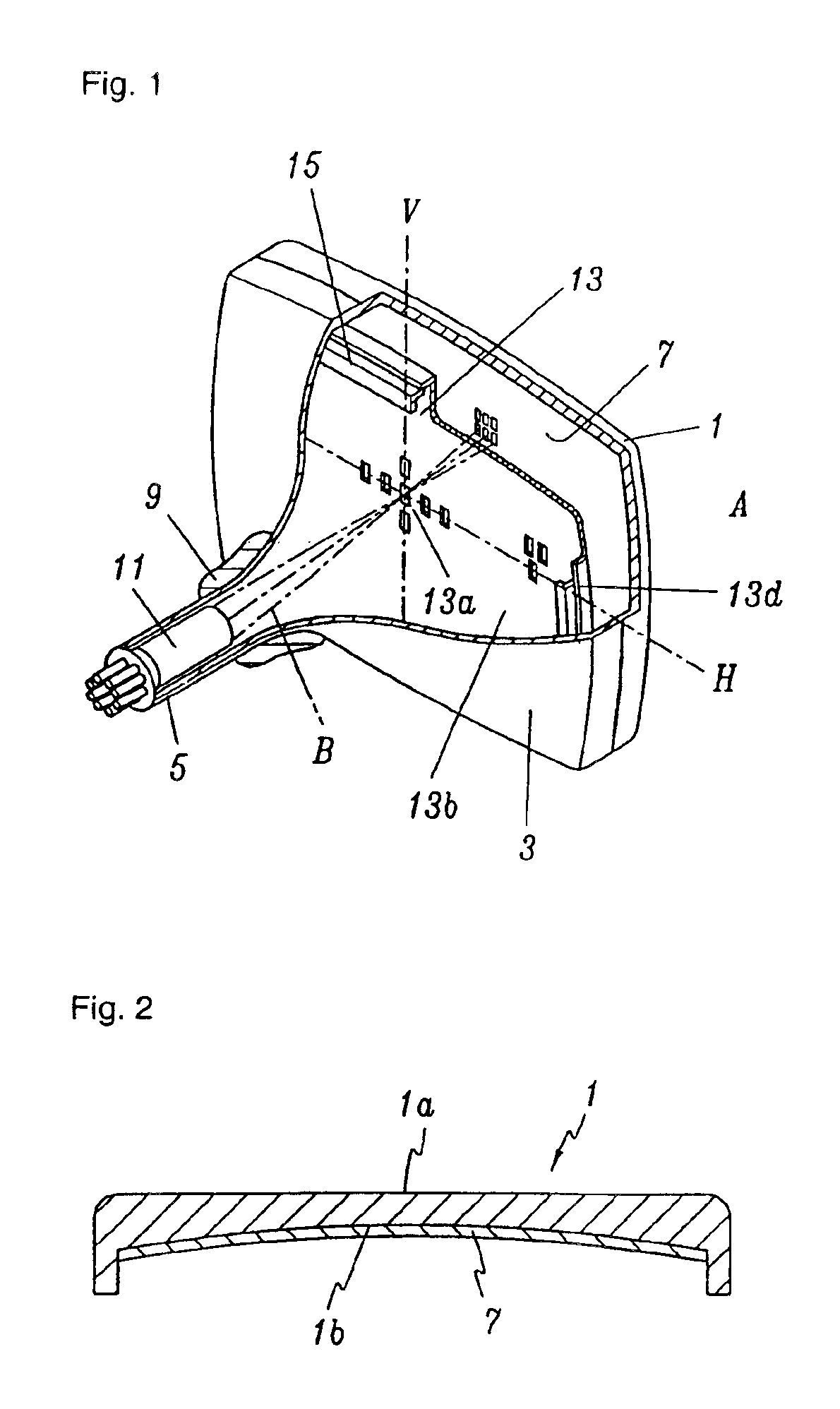
[0022]FIG. 1 is a partially cutaway perspective view of a cathode ray tube according to an embodiment of the present invention. As shown in the drawing, an exterior of the cathode ray tube (CRT) is defined by a panel 1, a funnel 3, and a neck 5, which are made of a glass material and fused into an integral, tube-like structure.

[0023]The panel 1 is substantially rectangular and a phosphor screen 7 is formed on an inner surface of the panel 1. The phosphor screen 7 includes a phosphor layer in a dot or striped pattern. With reference to FIG. 2, an outer surface 1a of the panel 1 is substantially flat, while an inner surface 1b of the panel 1 has a predetermined radius of curvature. In the case where the CRT is used as an image device for a display system such as a color television, such a shape of the panel 1 allows for realization of a picture with an exceptional three-dimensional and flat feel.

[0024]The funnel 3 fused to the panel 1 is, as its name suggests, funnel-shaped. A deflect...


PUM


Abstract

A shadow mask includes an aperture area having a plurality of apertures through which electron beams pass; a non-aperture area extending a from a circumference of the aperture area; and a skirt formed extending from an outer circumference of the non-aperture area at a predetermined angle, wherein the front surface of the aperture area is formed satisfying the following conditions,
100%<RMV′/RMV<110%
120%<RMS/RMV′<150%
where RMV is a vertical radius of curvature of the front surface of the aperture area with respect to a vertical direction passing through a center of the aperture area, RMS is a vertical radius of curvature with respect to a short side of the aperture area, and RMV′ is a vertical radius of curvature of the front surface of the aperture area with respect to the vertical direction at a location on a horizontal axis passing through the center of the aperture area.

Description

CROSS REFERENCE TO RELATED APPLICATIONS[0001]This application claims priority to and the benefit of Korean Patent Application No. 2002-0058395 filed on Sep. 26, 2002 in the Korean Intellectual Property Office, the entire disclosure of which is incorporated herein by reference.BACKGROUND OF THE INVENTION[0002](a) Field of the Invention[0003]The present invention relates to a shadow mask for a cathode ray tube. More particularly, the present invention relates to a shadow mask for a cathode ray tube, which is large and has a panel with a flat front surface, and to a cathode ray tube having such a shadow mask.[0004](b) Description of the Related Art[0005]A cathode ray tube (CRT) is used as an image device for a television, computer monitor, etc. A shadow mask used in a CRT performs a color selection function, in which selection of electron beams emitted from an electron gun is performed so that the electron beams land correctly on a phosphor surface. The shadow mask is structured corres...

Claims


Application Information

Patent Timeline
IPC IPC(8): H01J29/07
CPCH01J29/07H01J2229/0794H01J2229/0788
Inventor OH, HYUNG-SEOKKIM, DONG-HWAN
Owner SAMSUNG SDI CO LTD
Why Eureka
Try Eureka