Multicarrier distributed active antenna

a distributed active antenna and multi-carrier technology, applied in the field of active antenna arrays, can solve the problems of reducing the overall operating efficiency of the base station, adding cost and complexity to the passive antenna design, and almost half of the rf power delivered to the passive antennas is los

Inactive Publication Date: 2005-06-14
COMMSCOPE TECH LLC
View PDF144 Cites 248 Cited by
  • Summary
  • Abstract
  • Description
  • Claims
  • Application Information

AI Technical Summary

Problems solved by technology

Typically, for such high power systems or amplifiers, additional high power combiners must be used at the antennas which add cost and complexity to the passive antenna design.
The power losses experienced in the RF coaxial cables and through the power splitting at the tower top may necessitate increases in the power amplification to achieve the desired power output at the passive antennas, thereby reducing overall operating efficiency of the base station.
It is not uncommon that almost half of the RF power delivered to the passive antennas is lost through the cable and power splitting losses.
One problem encountered with distributed active antennas is that if one or more power amplifiers fail on the tower, the antenna elements associated with those failed power amplifiers become non-functional.
This results in a loss of radiated power for the distributed active antenna and also a change in the shape of the beam or beams formed by the antenna array.

Method used


Image

  • Multicarrier distributed active antenna
  • Multicarrier distributed active antenna
  • Multicarrier distributed active antenna

Examples


Embodiment Construction

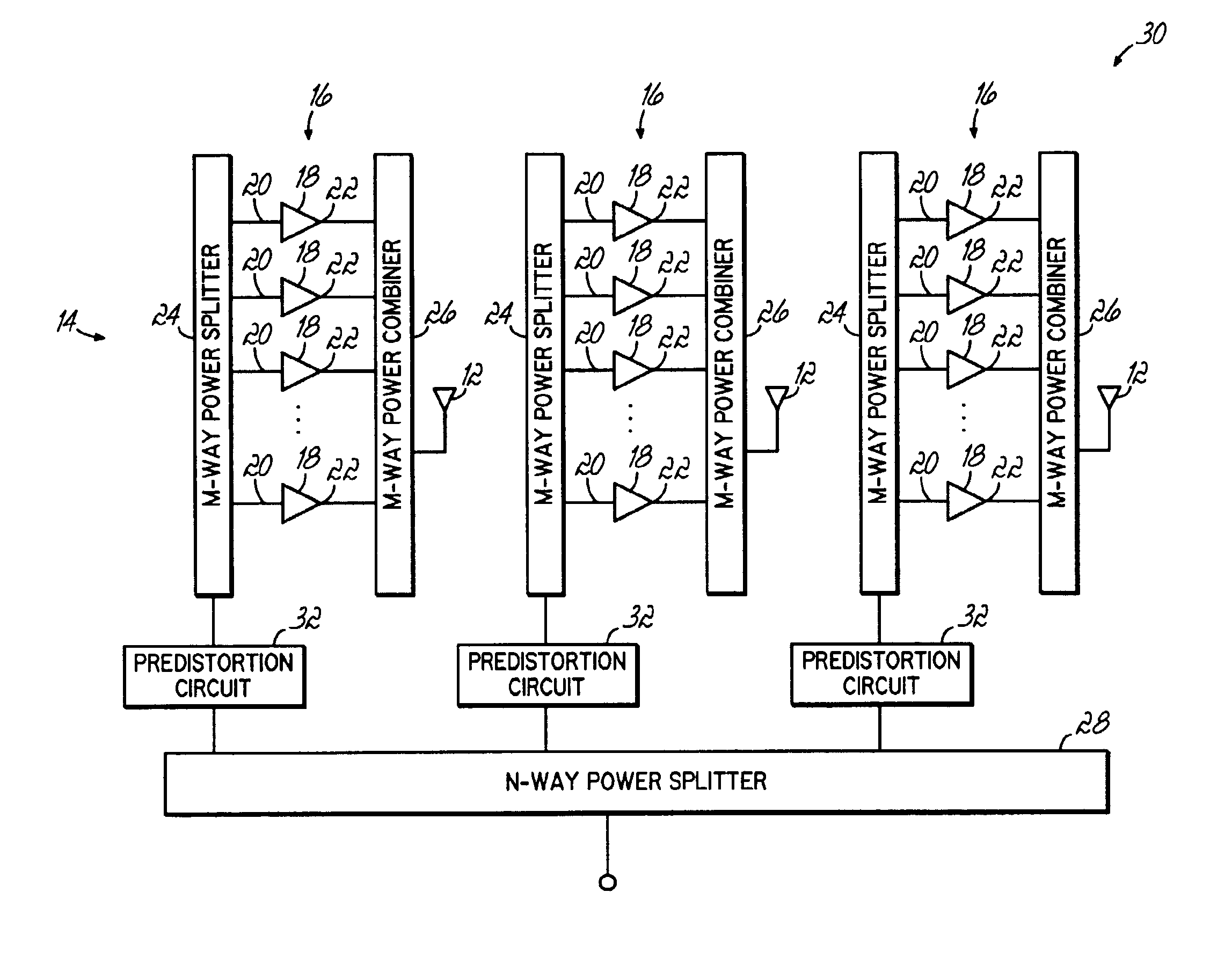
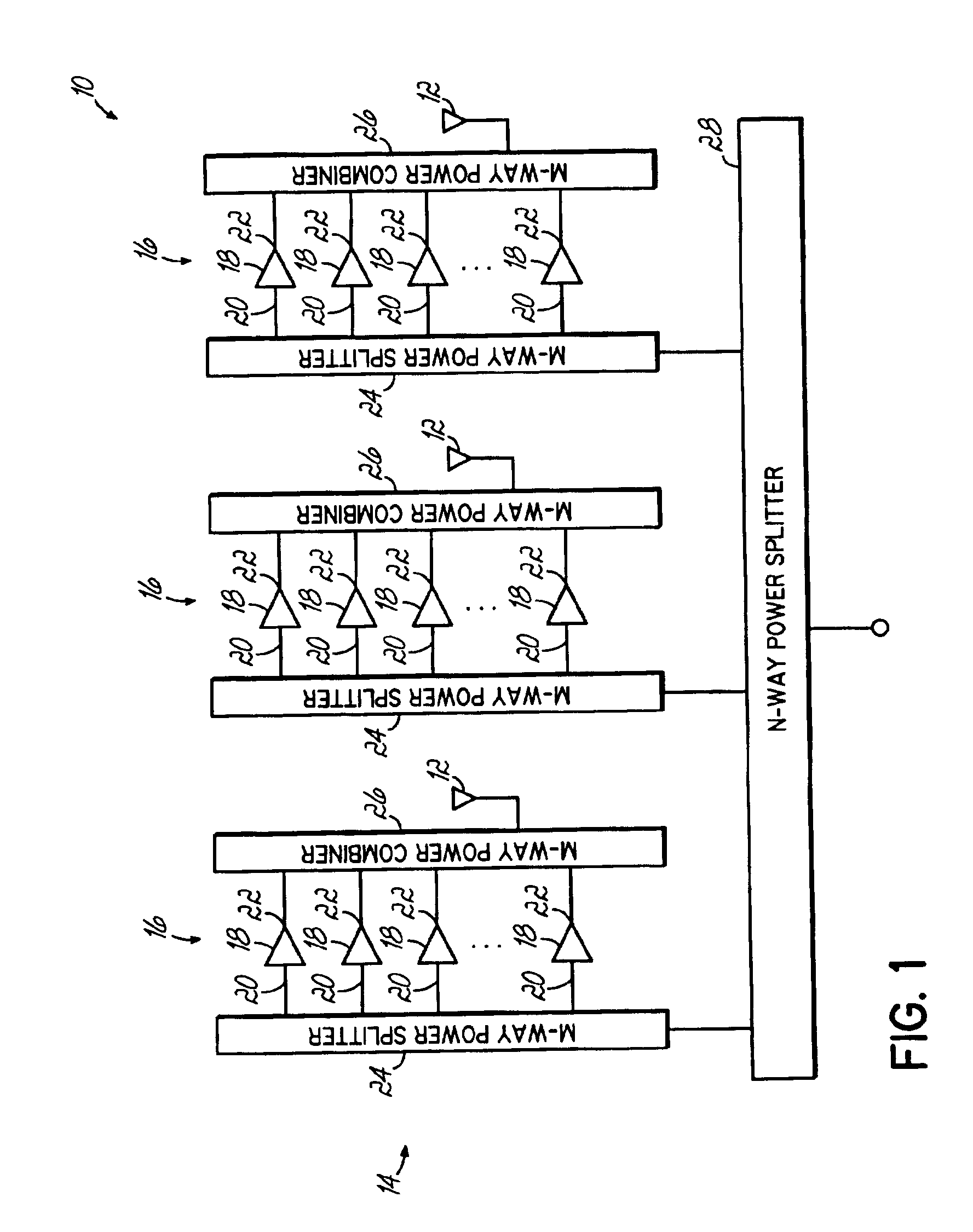
[0015]Referring now to the Figures, and to FIG. 1 in particular, a distributed active antenna 10 in accordance with one aspect of the present invention is shown. The distributed active antenna 10 comprises a sub-array 14 of N transmit antenna elements 12 that are arranged in either a vertical or horizontal column, although other configurations of the transmit antenna elements 12 are possible as well without departing from the spirit and scope of the present invention. It will be understood that components of the receive antenna elements associated with the distributed active antenna are not shown for purposes of clarity and only the transmit components of the distributed active array are described herein. Those of ordinary skill in the art will readily appreciate the components of the receive antenna elements suitable for use in the distributed active antenna 10 of the present invention.

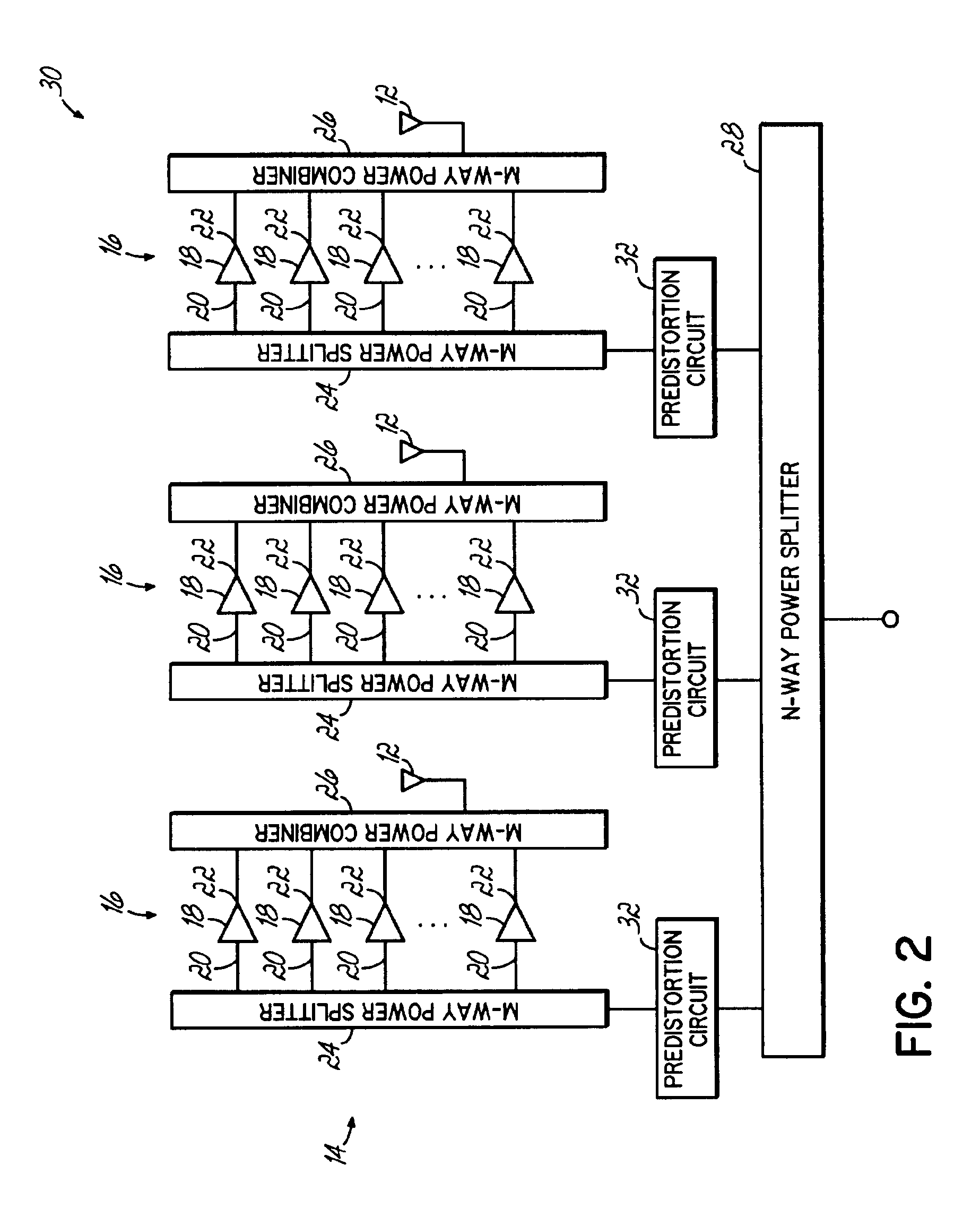
[0016]In this embodiment, each transmit antenna element 12 of the sub-array 14 is coupled to a re...


PUM


Abstract

A distributed active antenna includes a power module having a parallel combination of power amplifiers for driving each antenna element of the distributed active antenna. A predistortion linearization circuit may be coupled to each power module to linearize the output of each antenna element of the distributed active antenna.

Description

FIELD OF THE INVENTION[0001]The present invention relates generally to antenna systems used in the provision of wireless communication services and, more particularly, to an active antenna array adapted to be mounted on a tower or other support structure for providing wireless communication services.BACKGROUND OF THE INVENTION[0002]Wireless communication systems are widely used to provide voice and data communication between multiple mobile stations or units, or between mobile units and stationary customer equipment. In a typical wireless communication system, such as a cellular system, one or more mobile stations or units communicate with a network of base stations linked at a telephone switching office. In the provision of cellular services within a cellular network, individual geographic areas or “cells” are serviced by one or more of the base stations. A typical base station includes a base station control unit and an antenna tower (not shown). The control unit comprises the bas...

Claims


Application Information

Patent Timeline
Patent Type & Authority Patents(United States)
IPC IPC(8): H01Q23/00
CPCH01Q23/00
Inventor HOPPENSTEIN, RUSSELL
Owner COMMSCOPE TECH LLC
Why Eureka
Try Eureka