Assembly structure for image forming apparatus

Active Publication Date: 2005-06-14
BROTHER KOGYO KK
View PDF20 Cites 41 Cited by
  • Summary
  • Abstract
  • Description
  • Claims
  • Application Information

AI Technical Summary

Benefits of technology

[0011]According to the configuration, the image forming apparatus can be made compact in size and connection lines to the boards or the machines such as drive sources can be shortened. Particularly, the main control board is placed substantial

Problems solved by technology

This causes an increase in size of the image forming apparatus.
Thus, noise is easily produced from the harness and noise occurring from actuators of solenoids, motors, etc., is easily picked up by the harness.
If noise is thus picked up, a formed image easily becomes irregular.
Further, in a complex image forming apparatus provided by adding a facsimile function

Method used


Image

  • Assembly structure for image forming apparatus
  • Assembly structure for image forming apparatus
  • Assembly structure for image forming apparatus

Examples


Embodiment Construction

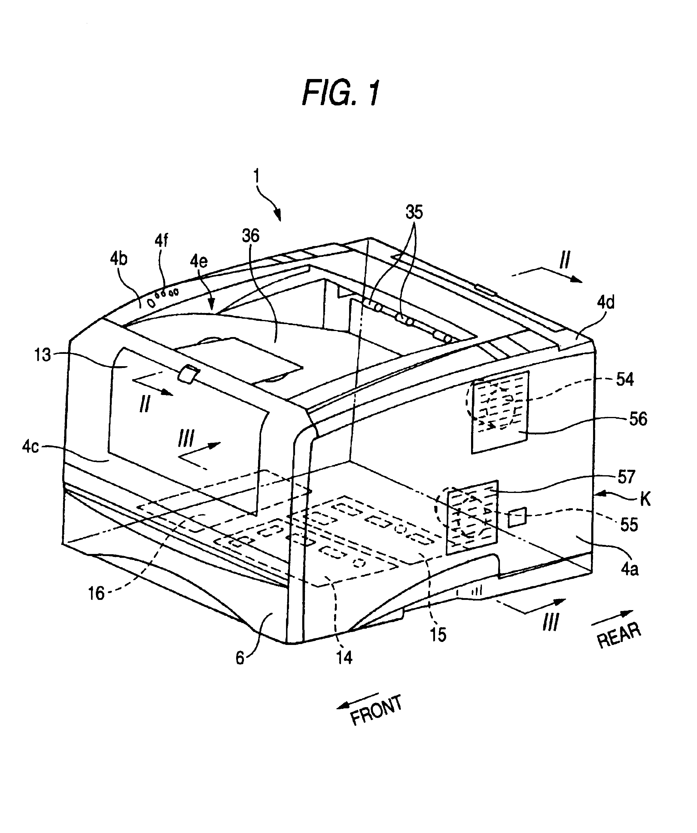
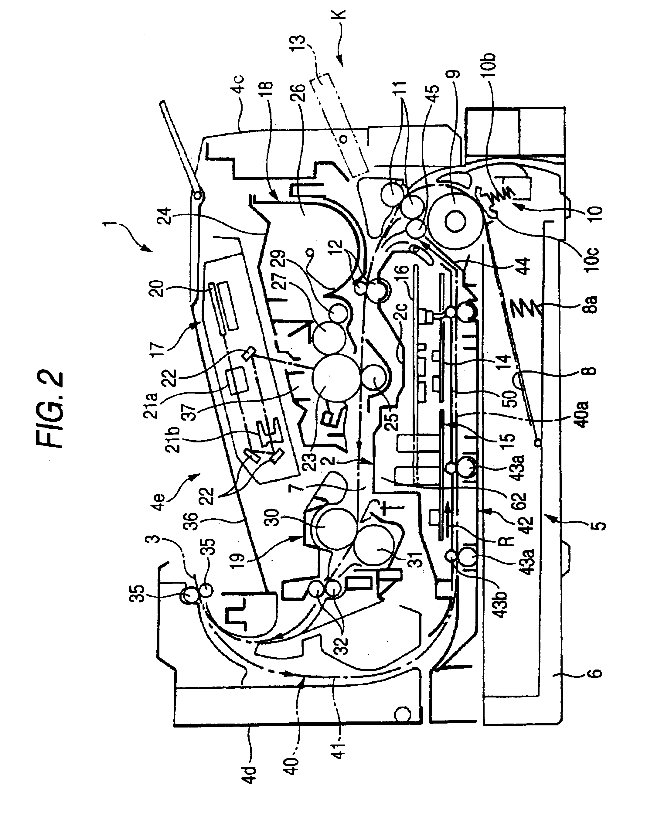
[0027]An embodiment of the invention will be described with reference to the accompanying drawings. FIG. 1 is a schematic perspective view showing a laser printer as an image forming apparatus according to an embodiment of the invention. In FIG. 1, an insertion side of a sheet feed tray (body front side) is shown as the left front. FIG. 2 is a sectional view taken along line II—II in FIG. 1. FIG. 3 is a sectional view taken along line III—III in FIG. 1. FIG. 4 is a perspective view of the laser printer turned upside down, when viewed from one direction. FIG. 5 is a perspective view of the laser printer turned upside down, when viewed from another direction. FIG. 6 is another schematic perspective view showing the laser printer. In FIG. 6, the rear of the body is shown as the left front.

[0028]FIG. 1 is a perspective view of a laser printer 1. In this embodiment, an insertion side of a sheet feed tray 6 described later is called a front side, and the opposite side is called a rear sid...


PUM


Abstract

An image forming apparatus includes a body frame having left and right side frame parts and a partition wall frame part that is placed below a sheet path passing through an image forming unit in a process unit. The process unit and a drive transmission system frame having a drive mechanism for transporting sheets are placed in a longitudinal direction on an outer face of the left side frame part. A high voltage power board, a low voltage power board, and an engine control board for the drive mechanism are fixedly placed horizontally on a lower face side of the partition wall frame part. A main control board is placed substantially vertically so as to become adjacent to the drive transmission system frame and extend along the outer face of the left side frame part. The boards and parts are connected by connection lines.

Description

BACKGROUND OF THE INVENTION[0001]1. Field of the Invention[0002]The present invention relates to an image forming apparatus such as a printer, a copier, or a facsimile apparatus, and more particularly to attaching positions and attitudes of circuit boards in an image forming apparatus.[0003]2. Description of the Related Art[0004]JP-A-10-143053 and JP-A-11-341203 disclose an electrophotographic image forming apparatus such as a laser printer or a laser facsimile in which an image forming unit is disposed in an upper side of a body frame and a plurality of circuit boards (control boards) are placed horizontally in a lower face side of the body frame.[0005]According to these related arts, as the number of circuit boards increases, the plan view area of the body frame must be enlarged to house the circuit boards. This causes an increase in size of the image forming apparatus.[0006]JP-A-10-143053 and JP-A-11-341203 further disclose that a low voltage power board, a high voltage power boa...

Claims


Application Information

Patent Timeline
IPC IPC(8): G03G15/00G03G21/18H05K7/14
CPCG03G15/80G03G2221/183G03G2221/1678G03G2221/166
Inventor HATTORI, YOSHITERUYOSHIHARA, HIDEOTSUSAKA, SHUSAKU
Owner BROTHER KOGYO KK
Why Eureka
Try Eureka