Floating structures

a technology of floating structures and floating walls, applied in the direction of bridges, special-purpose vessels, roads, etc., can solve the problems of inability to meet the needs of land use policies or community opposition, inability to meet the needs of land use policies, and inability to carry out construction and/or maintenance. to achieve the effect of reducing the effect of currents and reducing currents

Inactive Publication Date: 2005-06-21
GORMAN PATRICK HENRY
View PDF20 Cites 7 Cited by
  • Summary
  • Abstract
  • Description
  • Claims
  • Application Information

AI Technical Summary

Benefits of technology

[0007]One aspect of the invention is a floating structure comprising at least one deck; one or more flotation means attached to and supporting the deck; means for reducing the effects of currents in a body of water on the flotation means; and mooring means for restricting translational motion of the floating structure. In some embodiments, the means for reducing the effects of currents include ballast means for controlling flotation of the structure in a body of water; and mooring means for restricting translational motion of the floating structure.

Problems solved by technology

Similarly, floating bridges and roadways have been developed for use in, for example, locations where conventional bridge construction and / or maintenance would be undesirably costly or difficult, or where a relatively short bridge span is required.
Such structures, while portable, are apparently somewhat complex.
Development of additional permanent or temporary facilities for manufacturing, power generation, housing or other commercial use may be desirable, but not practical in view of land use policies or community opposition.

Method used


Image

  • Floating structures
  • Floating structures
  • Floating structures

Examples


Embodiment Construction

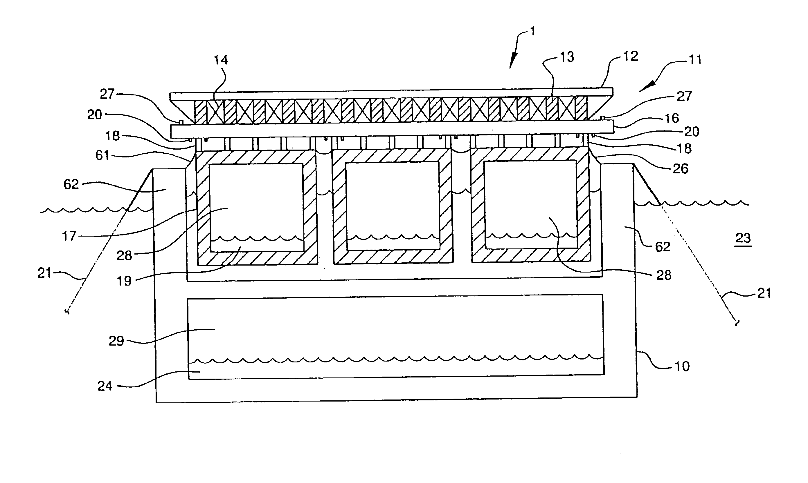
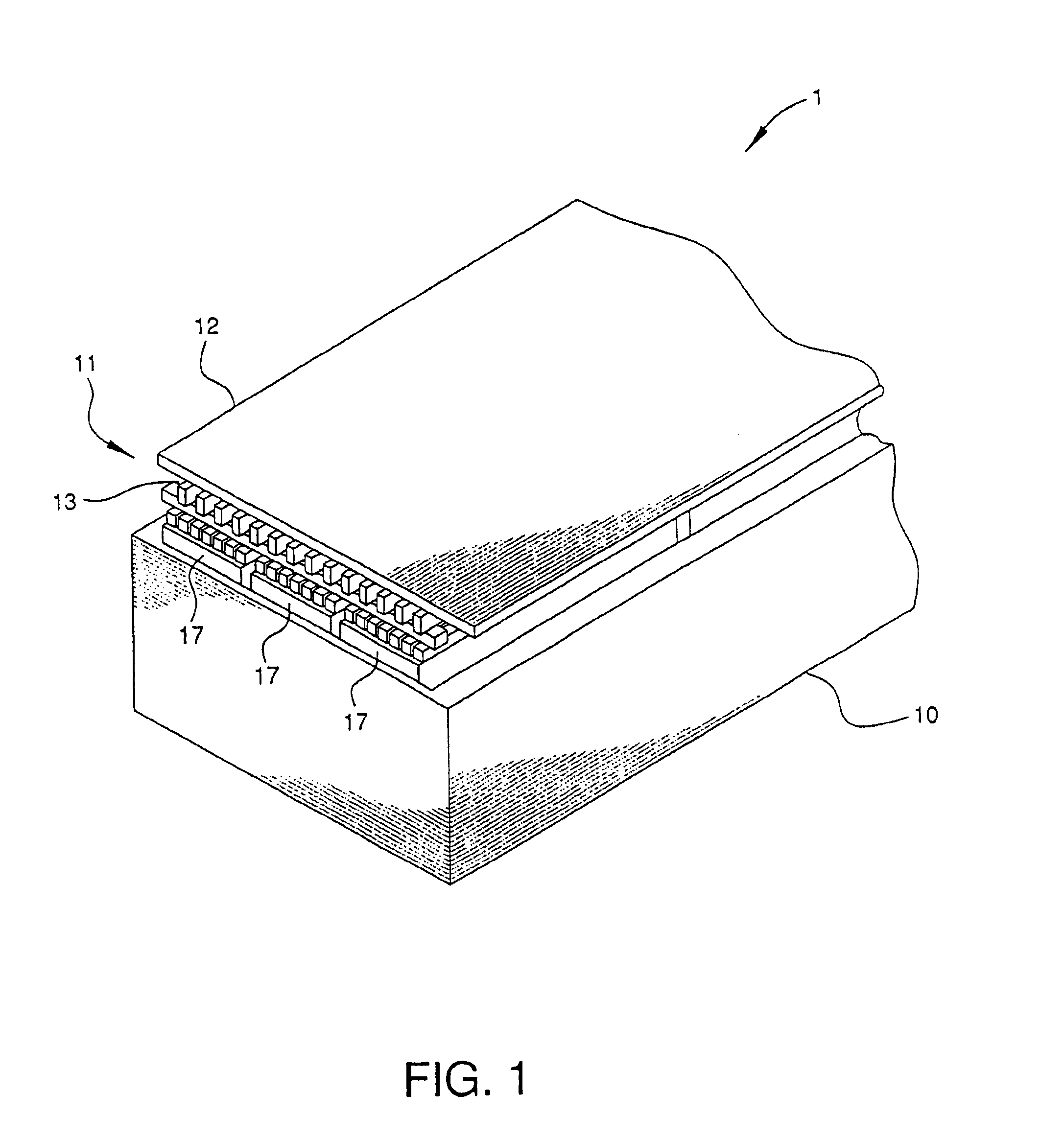
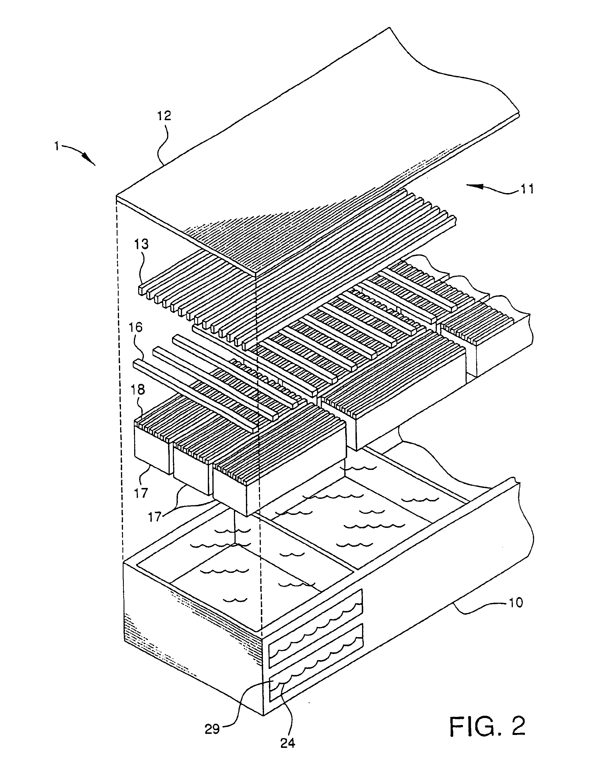
[0020]The present invention provides floating structures, also referred to herein as “floating platforms”, that are useful, for example, for airports, bridges, causeways, manufacturing facilities, electrical generating facilities, recreational and entertainment facilities, residential structures, waste disposal facilities, and other facilities. The floating platforms are particularly suited for airports, including airport runways, and aircraft landing strips because the structure of the platforms reduces the degree of motion caused by conditions such as prevailing winds, currents and tides in bodies of water, as compared to conventional floating structures such as barges and ships. The floating platforms are also particularly useful for bridges between land masses or between fixed or floating manmade structures.

[0021]A floating structure as disclosed herein includes at least one deck; one or more flotation means attached to and supporting the deck; and one or more means for reducing...


PUM


Abstract

Floating structures are provided. The floating structures are suitable for use as floating runways for aircraft, floating roadways, and supports for other facilities. The floating structures include a deck and one or more pontoons attached to the deck. The pontoons, with the deck attached, are caused to float in water contained in a basin, which in turn floats in a body of water. The basin provides damping or isolation of forces due to currents in the body of water, or prevailing winds, to reduce undesired or excessive motion of the deck. The deck supports are preferably capable of limited lateral movement relative to the pontoons, thereby permitting some movement of the pontoons independently and reducing stresses on the structure.

Description

RELATED APPLICATIONS[0001]This application is a continuation of application Ser. No. 10 / 109,153, filed Mar. 27, 2002 now U.S. Pat. No. 6,651,578.FIELD OF THE INVENTION[0002]The present invention relates to floating structures. In particular, the present invention relates to floating structures useful for maintaining platforms supporting airplane runways, bridges, or other structures afloat in bodies of water.BACKGROUND OF THE INVENTION[0003]Constraints such as shortages of available land when there is a need to locate a structure, either temporarily or permanently, either adjacent to land, or in a large body of water, have led to the development of floating platforms and the like that can support a structure on a body of water. For example, floating runways such as that disclosed in U.S. Pat. No. 5,906,171 provide water-borne surfaces for aircraft to land and take off, similar to surfaces on aircraft carriers. Floating airports, such as that disclosed in U.S. Pat. No. 5,398,635, can...

Claims


Application Information

Patent Timeline
Patent Type & Authority Patents(United States)
IPC IPC(8): B63B35/52B63B35/44B63B35/00E01C3/00B63B35/34B63B35/50B63B35/53E01D15/14
CPCB63B35/52B63B35/44
Inventor GORMAN, PATRICK HENRY
Owner GORMAN PATRICK HENRY
Why Eureka
Try Eureka