Torque limiting coupling device

a coupling device and torque limit technology, applied in the direction of couplings, engine lubrication, shafts, etc., can solve the problems of clogging valves, filter blockage, and affecting the function of the device, and achieve the effect of ensuring the device is not damaged and re-used

Inactive Publication Date: 2005-06-21
CURT FALK AB
View PDF9 Cites 5 Cited by
  • Summary
  • Abstract
  • Description
  • Claims
  • Application Information

AI Technical Summary

Benefits of technology

[0015]The coupling can be readily renovated subsequent to plasticization (which may lead to melting of the surface layer), by heating said layer and that part (the shaft) that carries the surface layer. Because the surface layer is comprised of material (tombak) that has a high coefficient of thermal expansion, the layer will loosen from the base of said part (the shaft) and be easily drawn off the shaft. A replacement surface layer in the form of a tombak-sleeve can be simply inserted into / pushed over the part concerned (10, 20) and fastened thereto by means of a glue joint, for instance, this joint being destroyed by the heat applied in the renovating process or in conjunction with plasticization of the surface layer.

Problems solved by technology

Problems associated with this known device reside in the possibility of all or part of the liquid / oil contained in the device leaking away before the device is triggered, or of by a change in the properties of the oil with time, contamination of the oil with particles that can be formed, for instance, in conjunction with triggering the device and that clog valves, filters, and disturb or interfere with the function of the device, and so on.
There is therefore a certain risk that this known device will malfunction when triggered.
Malfunctioning of the device would mean that the mutually interacting surfaces would not be separated sufficiently and that insufficient oil would be pressed in between the interacting surfaces.
The malfunction may then cause a very high torque to be transferred via the device in spite of the torque-limiting mechanism, therewith resulting in damage to the motor and driven equipment for instance, and also such as to cause serious damage to the coupling device itself.
Particularly with a view to the consequence of such a malfunction (compare the idling cost), the type of device concerned has not found particularly wide use in practice, despite the ability of the device to enable automatic and fast resetting with normal triggering of the device, and thereby a fast return to plant operation after having removed or rectified the triggering cause.

Method used


Image

  • Torque limiting coupling device
  • Torque limiting coupling device

Examples


Embodiment Construction

[0018]Further scope of the applicability of the present invention will become apparent from the detailed description given hereinafter. However, it should be understood that the detailed description and specific examples, while indicating preferred embodiments of the invention, are given by way of illustration only, since various changes and modifications within the spirit and scope of the invention will become apparent to those skilled in the art from this detailed description.

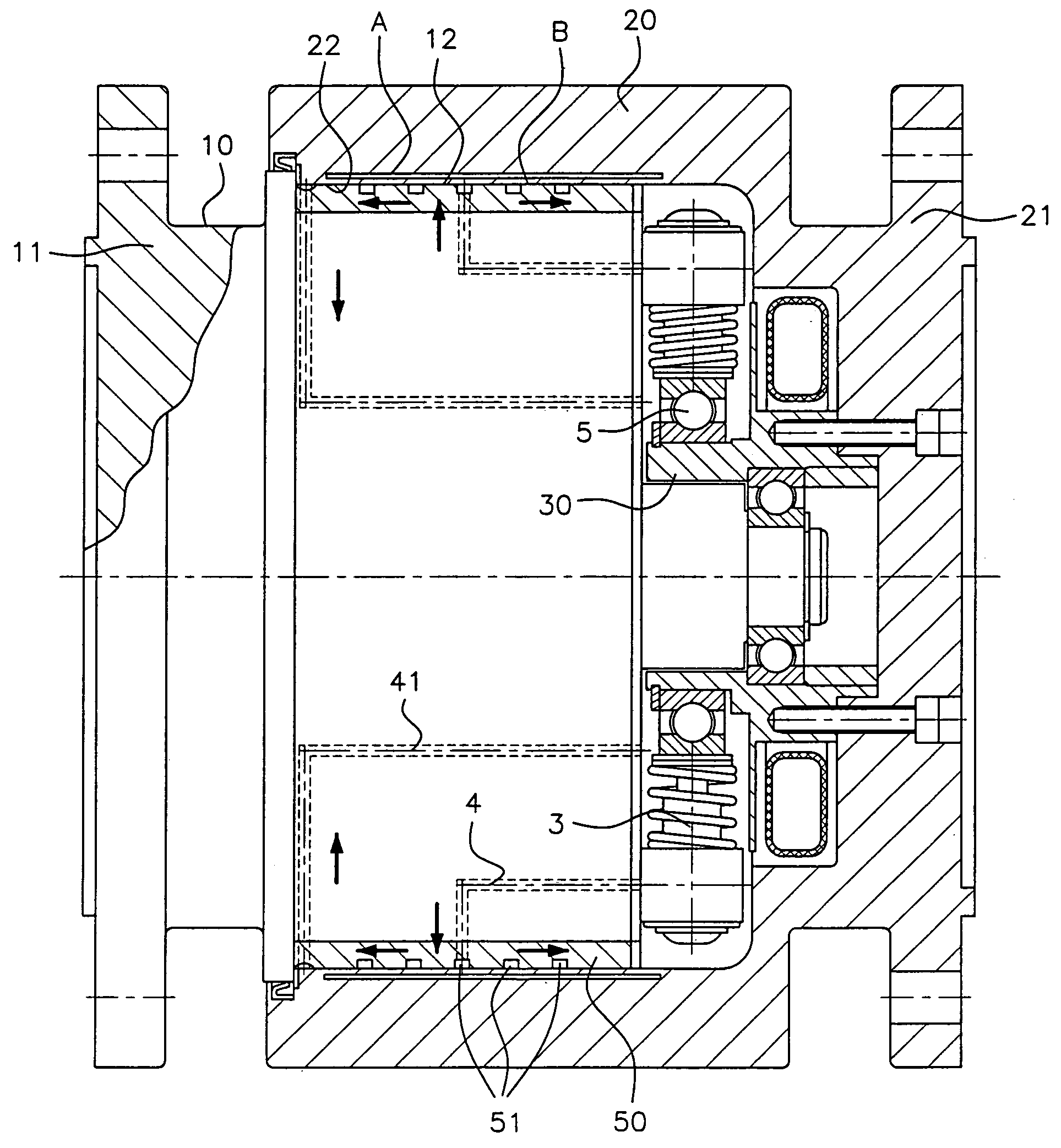
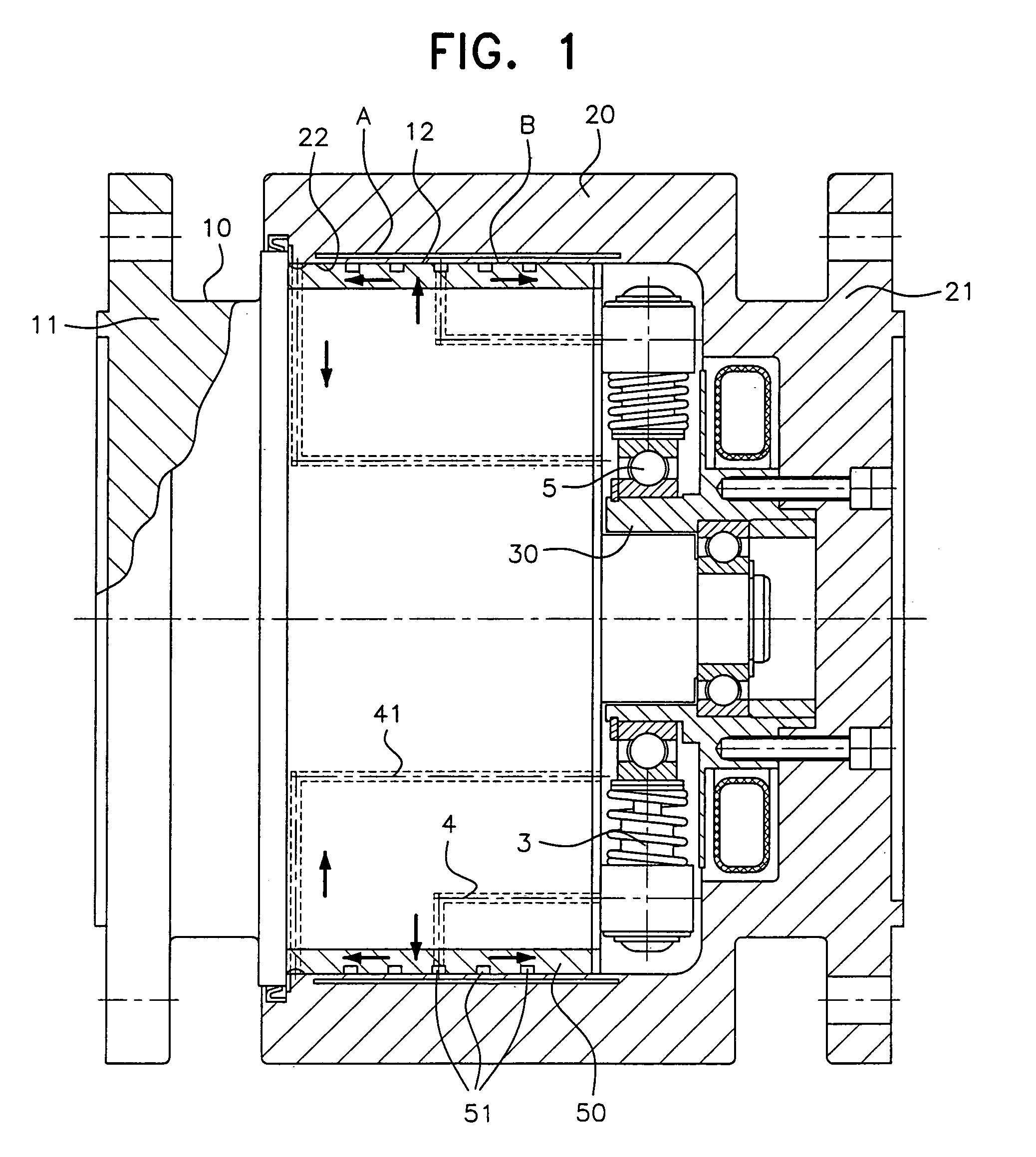
[0019]The device illustrated in FIG. 1 is based fundamentally on the device according to U.S. Pat. No. 5,069,320 to Falk, the teachings of which are hereby incorporated in this document by reference as if fully set forth herein. In particular, the subject matter of U.S. Pat. No. 5,069,320 (the '320 patent) is relied upon as fully describing a pump mechanism that, in response to relative rotation between a cylindrical sleeve fitted on a cylindrical part, pumps liquid between the engagement surfaces of the slee...


PUM


Abstract

A torque-limiting coupling device including a cylindrical sleeve and a cylindrical shaft in radially tensioned frictional engagement for transferring torque up to a torque limit that corresponds to the radial tension and at which the sleeve begins to rotate relative to the shaft. The device also includes at least one pump mechanism which is adapted to be driven to pump liquid to the interface between co-acting surfaces of the sleeve and shaft upon relative rotation between the sleeve and the shaft. The shaft includes a surface layer that defines one of the co-acting surfaces and that is made of a material, e.g. tombak, whose plasticizing limit is lower than the plasticizing limit of the material in the co-acting surface of the sleeve. The surface layer may include cavities which enable the surface layer to take a smaller radial thickness after plasticization thereof.

Description

[0001]This is a nationalization of PCT / SE00 / 02101, filed Oct. 27, 2000 and published in English.BACKGROUND OF THE INVENTION[0002]1. Field of the Invention[0003]The present invention relates to a torque-limiting coupling device having two coaxial, generally cylindrical co-acting surfaces on two co-acting parts in the form of a cylindrical sleeve and a cylindrical shaft, respectively. The sleeve is in frictional engagement with the shaft for transmission of torque up to a limit that corresponds to the frictional engagement and at which the sleeve begins to rotate relative to the shaft. The device further includes a pump mechanism which, upon relative rotation between the sleeve and the shaft, is driven to pump liquid to an interface between the co-acting surfaces, with channels being provided to carry away liquid from the interface so as to restore the frictional grip after the torque limit has been exceeded.[0004]2. Description of the Related Art[0005]A coupling device of the kind in...

Claims


Application Information

Patent Timeline
Patent Type & Authority Patents(United States)
IPC IPC(8): F16D43/21F16D43/00F16D7/02F16D7/00
CPCF16D43/21
Inventor FALK, CURT
Owner CURT FALK AB
Why Eureka
Try Eureka