Switching constant-current power supply

a constant-current power supply and switch technology, applied in constant-current supply dc circuits, instruments, process and machine control, etc., can solve the problems of unstable load current, long time required before, and load current greater than the stabilization target value will flow for a comparatively long time, so as to achieve the effect of stabilizing the load curren

Inactive Publication Date: 2005-06-21
TOKYO
View PDF7 Cites 46 Cited by
  • Summary
  • Abstract
  • Description
  • Claims
  • Application Information

AI Technical Summary

Benefits of technology

[0013]Accordingly, it is an object of this invention to provide a switching constant-current p

Problems solved by technology

When the on-duty reaches its maximum during the current cut-off period, the voltage between the terminals of the smoothing capacitor C1 abruptly increases, and, in the subsequent current flow period, there is a possibility that a load current greater than the stabilization target value will flow for a comparatively long time.
Consequently, in the event of an interrupted non-cyclical load or other such load fluctuation, a long tim

Method used


Image

  • Switching constant-current power supply
  • Switching constant-current power supply
  • Switching constant-current power supply

Examples


Embodiment Construction

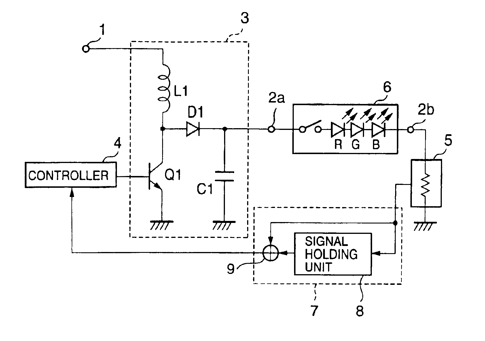
[0024]FIG. 1 shows a preferred embodiment of the switching constant-current power supply of this invention.

[0025]The switching constant-current power supply shown in the block diagram of FIG. 1 is identical to that shown in FIG. 4, with the exception that a feedback circuit 7 is provided between the controller 4 and the detector 5. The constitution of the feedback circuit 7 of FIG. 1 broadly divides into a signal holding unit 8 for creating a second feedback signal, and a selecting unit 9 for supplying to the controller 4 either a first feedback signal output from the detector 5, or the second feedback signal.

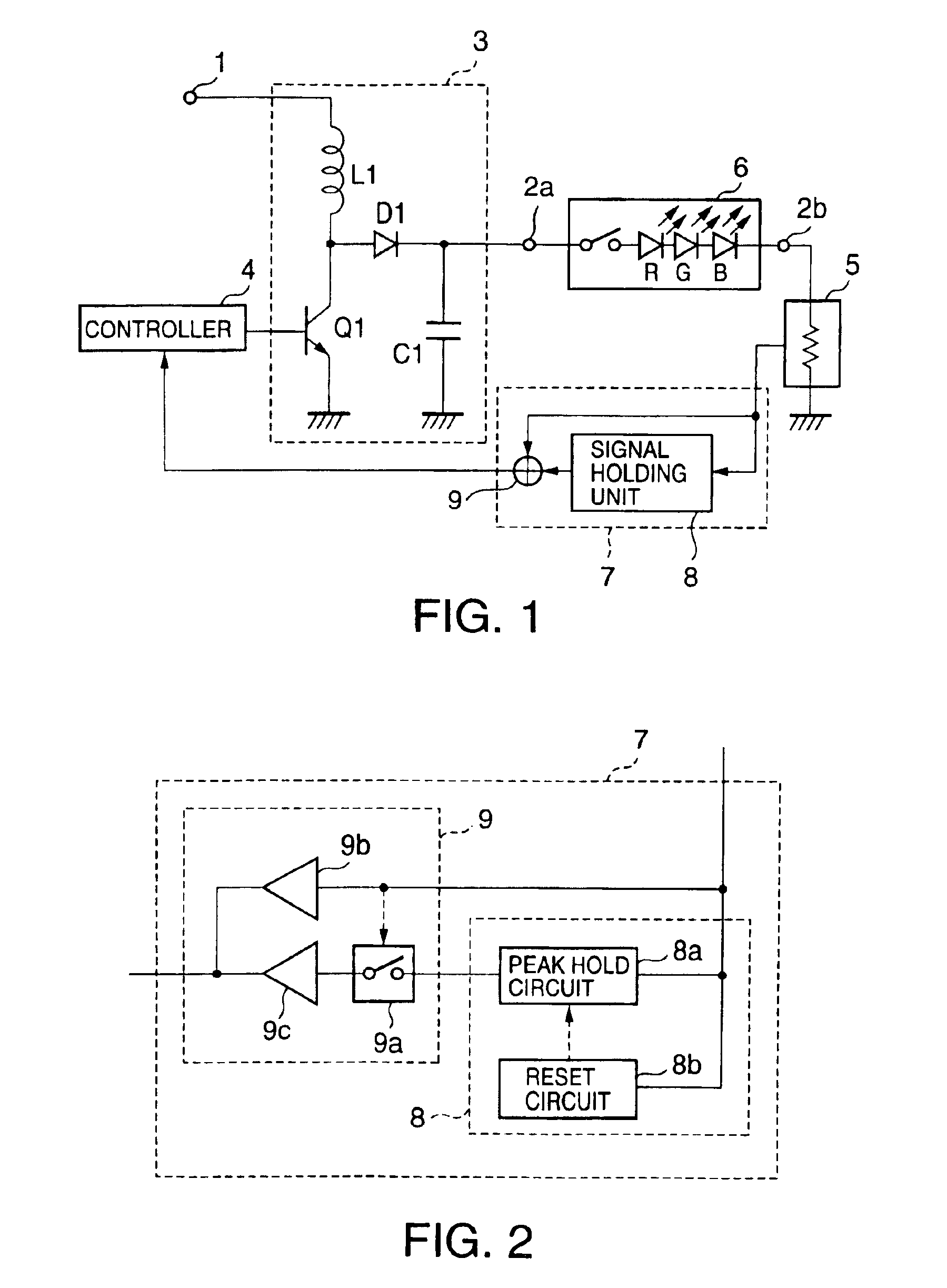
[0026]FIG. 2 is a block diagram showing the specific constitution of the feedback circuit 7 having the above functions.

[0027]In FIG. 2, reference numerals 8a and 8b respectively represent a peak hold circuit and a reset circuit, which together constitute the signal holding unit 8, and reference numerals 9a, 9b, and 9c respectively represent a switch circuit, a first buffer circ...


PUM


Abstract

Disclosed herein is a switching constant-current power supply which comprises: a switching-system power converter for supplying a predetermined current to a load; a current detector for generating a feedback signal in correspondence with the load current; a controller for driving the power converter in correspondence with the feedback signal; and a feedback circuit, which is provided between the current detector and the controller, and comprises a signal holding unit, the feedback circuit supplying either a first feedback signal, output from the current detector, or a second feedback signal, output from the signal holding unit, to the controller; the size of the second feedback signal being approximately equal to the first feedback signal at a given time.

Description

BACKGROUND OF THE INVENTION[0001]1. Field of the Invention[0002]This invention relates to a switching-system constant-current power supply for supplying a stable current to an intermittent load.[0003]2. Description of the Related Art[0004]When using a light-emitting diode (hereinafter “LED”) as a light source, the current supply to the LED must be stabilized in order to obtain a constant amount of emitted light, brightness, and the like. As an example, FIG. 4 shows the constitution of a switching constant-current power supply, conventionally used for supplying this type of stabilized current to a load.[0005]In FIG. 4, reference numeral 1 represents an input terminal for receiving power supplied from an external battery, and reference numerals 2a and 2b represent output terminals for stably supplying predetermined current to a load 6 having a plurality of LEDs, connected between them. A power converter 3 is connected between the input terminal 1 and the output terminal 2a, and forms ...

Claims


Application Information

Patent Timeline
IPC IPC(8): H02M3/04H02J1/04H02M3/156H05B33/02H05B33/08H02M3/155H02M3/325
CPCH02J1/04H05B33/0815H02M3/1563H05B45/38
Inventor OTAKE, TETSUSHI
Owner TOKYO
Why Eureka
Try Eureka