Antenna device

a technology of antennas and antenna elements, applied in the direction of resonant antennas, independent non-interacting antenna combinations, radiating element structural forms, etc., can solve the problems of limited space for internal antenna arrangements and unwanted coupling between antennas, and achieve the effect of minimising the electrical coupling between transmitting and receiving antenna elements

Inactive Publication Date: 2005-06-21
SAMSUNG ELECTRONICS CO LTD
View PDF8 Cites 33 Cited by
  • Summary
  • Abstract
  • Description
  • Claims
  • Application Information

AI Technical Summary

Benefits of technology

[0007]An object of the present invention is to provide an antenna device for use in a radio communication device, preferably a portable radio communication device, wherein the electrical coupling between transmit and receive antenna elements is minimised.
[0008]The invention is based on the realisation that when one antenna element has a balanced feed and another antenna element has an unbalanced feed, it is possible to design the two antennas in a way in which the coupling between the antennas can be lower than with two antennas both having unbalanced or balanced feed.
[0009]An advantage with a balanced and unbalanced antenna pair is that with a balanced input to receiver electronic circuits and an unbalanced feeding from an output amplifier, lower losses and improved matching to the receiver / transmitter are achieved.

Problems solved by technology

In a portable radio communication device the space for an internal antenna arrangement is limited.
With closely spaced antenna elements unwanted coupling between the antennas can arise.

Method used


Image

  • Antenna device
  • Antenna device
  • Antenna device

Examples


Embodiment Construction

[0023]In the following, a detailed description of preferred embodiments of an antenna device according to the invention will be given. In the several embodiments described herein, the same reference numerals are given to identical parts of the different embodiments.

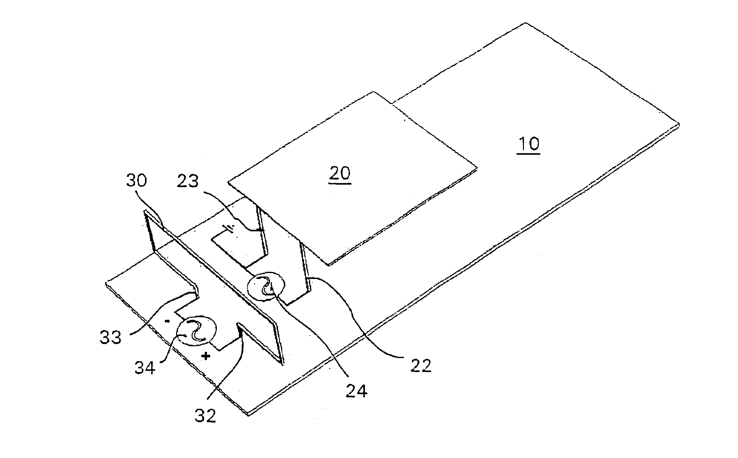
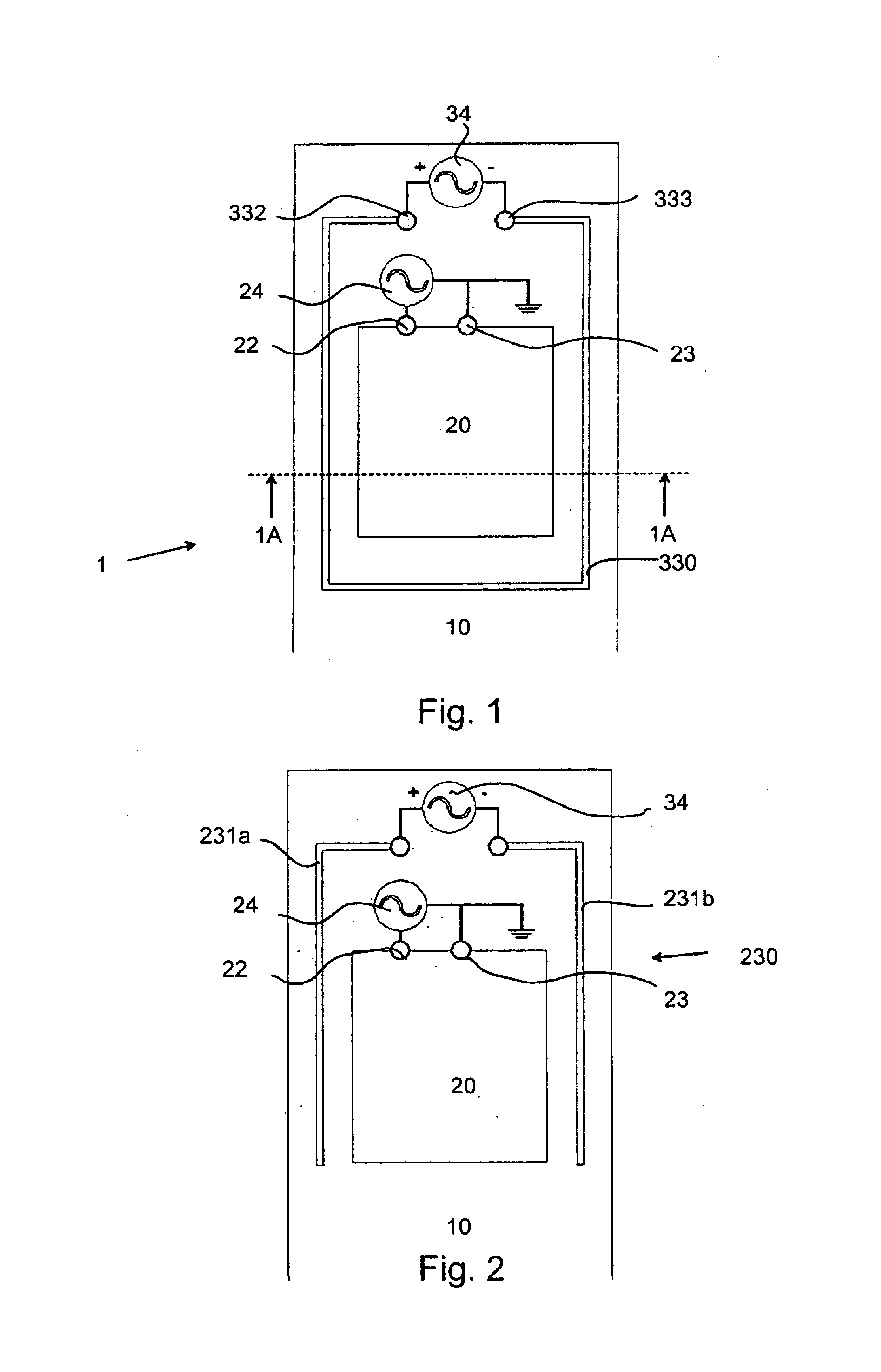
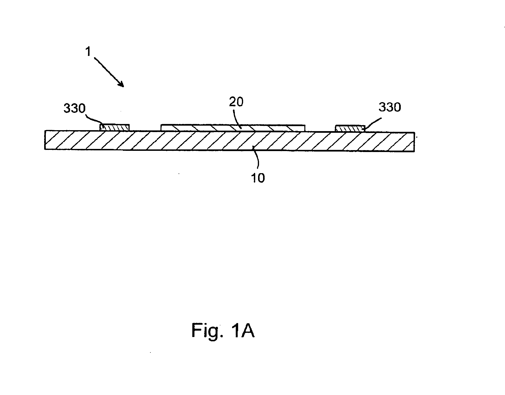
[0024]A balanced feed is defined as when a transmission line, comprising two conductors in the presence of ground, is capable of being operated in such a way that when voltages of the two conductors at all transverse planes are equal in magnitude and opposite in polarity with respect to ground, currents in the two conductors are essentially equal in magnitude and opposite in direction. An unbalanced feed is defined as a feed that does not fulfil the above criteria.

[0025]Reference is first made to FIG. 1, wherein an antenna device or module, generally designated 1, comprises a printed circuit board (PCB) 10, having mounted thereon circuits for the transmitter portion 24 and the receiver portion 34 of the electronic circuit...


PUM


Abstract

An antenna device for a radio communication device, preferably a portable radio communication device, comprising a first antenna element (20) comprising a first feeding portion (22) connected to a first feeding device (24), a second antenna element (30; 230; 330; 430; 530; 630) comprising second feeding portions (32, 33; 332, 333) connected to a second feeding device (34), wherein said first antenna element (20) has an unbalanced feed, and said second antenna element (30; 230; 330; 430; 530; 630) has an essentially balanced feed.

Description

[0001]This is a nationalization of PCT / SE01 / 01600 filed Jul. 10, 2001 and published in English.FIELD OF INVENTION[0002]The present invention relates generally to antenna devices and more particularly to an antenna device for use in a radio communication device, such as a mobile phone.BACKGROUND[0003]In a portable radio communication device the space for an internal antenna arrangement is limited. With the growing need for greater functionality and better radio channel quality it is often necessary to utilise more than one antenna element in a portable radio communication device, such as a mobile telephone. Because of the limited space in a portable radio communication device, internal antennas tend to be closely spaced. With closely spaced antenna elements unwanted coupling between the antennas can arise.[0004]Low coupling between closely spaced antennas is necessary for various applications. These can be for example: separate RX and TX antenna system which eliminates the need for a...

Claims


Application Information

Patent Timeline
Patent Type & Authority Patents(United States)
IPC IPC(8): H01Q1/38H01Q9/28H01Q9/04H01Q9/26H01Q21/28H01Q1/24H01Q9/16H01Q7/00H01Q21/00
CPCH01Q1/243H01Q1/38H01Q7/00H01Q9/0421H01Q21/28H01Q9/265H01Q9/28H01Q9/285H01Q9/16H01Q13/08
Inventor RUTFORS, TOMASBRAUN, CHRISTIANFALKEN, HENRIKH.ANG.KANSSON, LENNARTDONGHUI, LIUTHORNELL-PERS, ANDERS
Owner SAMSUNG ELECTRONICS CO LTD
Why Eureka
Try Eureka