Time-to-voltage converter

a time-to-voltage converter and converter technology, applied in the field of time-to-voltage converters, can solve the problems of complex circuits, circuit becomes more nonlinear, digital circuits interfere with the proper operation of switches, etc., and achieve the effect of low nonlinearity

Inactive Publication Date: 2005-06-21
GE GLOBAL RES
View PDF2 Cites 23 Cited by
  • Summary
  • Abstract
  • Description
  • Claims
  • Application Information

AI Technical Summary

Problems solved by technology

This typically requires complicated circuits, such as high-speed PLLs.
One of the problems in the time-to-voltage converter described above is that as delta T becomes smaller, the circuit becomes more nonlinear due to incomplete switch transitions.
A similar problem occurs if an event occurred just after the rising edge of the clock.
Even though the width of the pulse in this case is much larger than the rise and fall times, the transition of the clock in the digital circuit will interfere with proper operation of the switches.
As can be seen from the timing diagram of the traditional time-to-voltage converter, shown in FIG. 3, there is no way to prevent this from occurring when random events are input to the system.

Method used


Image

  • Time-to-voltage converter
  • Time-to-voltage converter
  • Time-to-voltage converter

Examples


Embodiment Construction

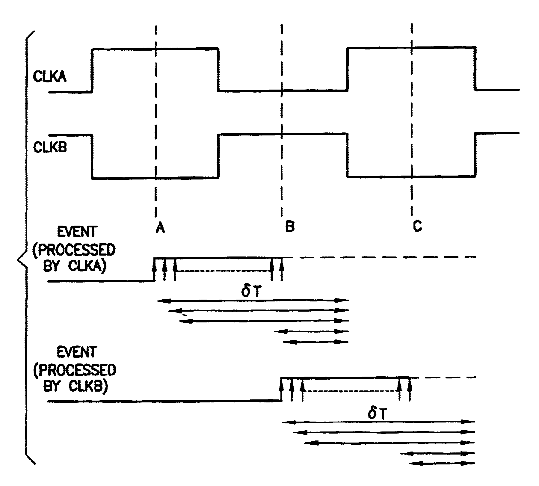
[0031]Consider the normal operation mode of a time-to-voltage converter when an input event causes the current controlling switch to close in order to charge the integrating capacitor and develop a corresponding voltage. In the embodiments disclosed below, two clocks offset from each other in phase only are utilized in such a way that the case of a clock edge being too close to the event edge can be avoided. This is the principle of a two-phase time-to-voltage converter.

[0032]Respective system level representations of two-phase time-to-voltage converter circuits that obey the general rules described above to yield a very linear time-to-voltage conversion are shown in FIGS. 4 and 5. FIG. 6 shows the timing diagram for the operation of these circuits.

[0033]Referring to FIG. 4, Channel A comprises a current source 10a, an integrating capacitor 12a, a single-pole double-throw START / STOP switch 16a, and a time-to-voltage amplifier 20a, whereas Channel B comprises a current source 10b, an...


PUM


Abstract

A time interval to voltage converter with very low nonlinearity for time stamping events. The converter automatically selects one of two clocks related to a reference clock and ensures that the time between an event edge to a clock edge is sufficiently large to properly operate a switch and yield very linear time-to-voltage conversion.

Description

BACKGROUND OF THE INVENTION[0001]This invention generally relates to time stamping of events in computerized systems. In particular, the invention relates to time stamping of events in imaging systems used in medical diagnostics.[0002]Modern medical diagnostic imaging systems typically include circuitry for acquiring image data and for transforming the data into a useable form, which is then processed to create a reconstructed image of features of interest within the patient. The image data acquisition and processing circuitry is referred to as a “scanner”, regardless of the modality, if physical or electronic scanning occurs as part of the imaging process. The particular components of the system and related circuitry, of course, differ greatly between modalities due to their different physics and data processing requirements.[0003]Positron emission tomography (PET) is an imaging modality based on the detection of gamma ray pairs produced by annihilation of a positron and electron w...

Claims


Application Information

Patent Timeline
Patent Type & Authority Patents(United States)
IPC IPC(8): G01T1/20G01T1/161G01T1/00G04C21/00G04F10/00G04C21/16G04F10/10H03K5/22H03M1/66G01T1/29
CPCG04F10/10G01T1/2985
Inventor RAO, NARESH KESAVAN
Owner GE GLOBAL RES
Why Eureka
Try Eureka