Magneto-optical recording apparatus having a magnetic head with a regulating member

a technology of magnetic head and regulating member, which is applied in the field of magnetic head provided magnetic recording apparatus, can solve problems such as obstructing high frequency recording, and achieve the effect of reducing the size of the magnetic pole core and high frequency recording

Inactive Publication Date: 2005-06-21
CANON KK
View PDF7 Cites 14 Cited by
  • Summary
  • Abstract
  • Description
  • Claims
  • Application Information

AI Technical Summary

Benefits of technology

[0010]An object of the present invention is to provide a magneto-optical recording apparatus permitting a reduction in magnetic pole core size by regulating the displacement of the magnetic head in a direction parallel to the surface of the recording medium, and making possible high frequency recording.

Problems solved by technology

Since it is necessary to prevent the irradiating beam from being off the magnetic pole core 6 even if the magnetic pole core 6 deviates, the size of the magnetic pole core 6 has to be increased, eventually giving rise to a problem of obstructing high frequency recording.

Method used


Image

  • Magneto-optical recording apparatus having a magnetic head with a regulating member
  • Magneto-optical recording apparatus having a magnetic head with a regulating member
  • Magneto-optical recording apparatus having a magnetic head with a regulating member

Examples


embodiment 1

(Embodiment 1)

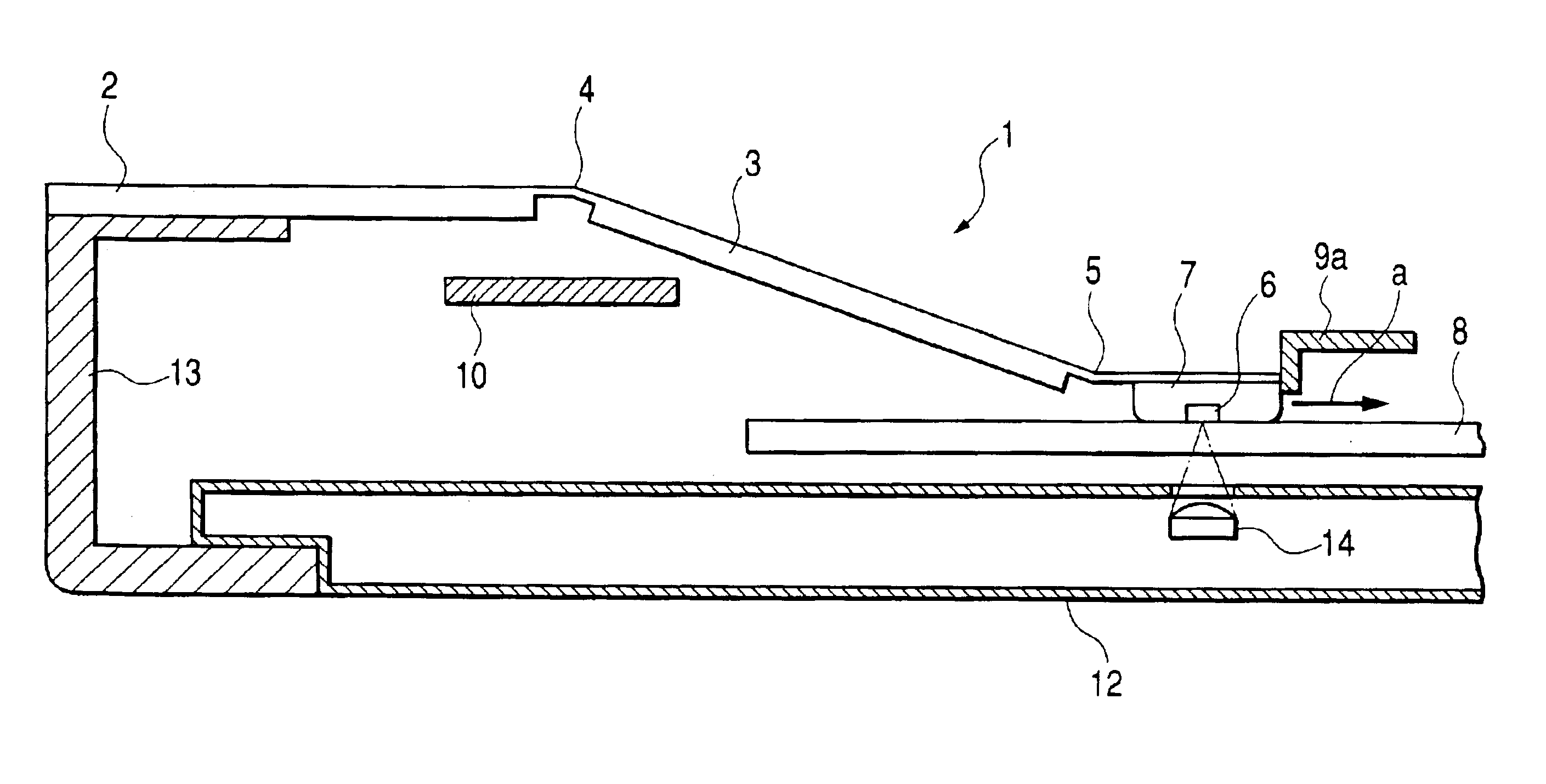
[0048]FIG. 4 and FIG. 5 illustrate a magneto-optical recording apparatus, which is a first embodiment of the present invention. FIG. 4 shows a sectional view of the loaded state of the magnetic head 1, and FIG. 5, a sectional view of the unloaded state of the magnetic head 1. To add, in FIG. 4 and FIG. 5, the same parts as their counterparts in the prior art apparatus shown in FIG. 1 and FIG. 2 are designated by respectively the same reference characters, and their description is dispensed with.

[0049]In Embodiment 1, one end of a load beam 3 is supported by the base 2 of the magnetic head 1 via a first leaf spring 4, and to the other end of the load beam 3 is fitted via a second leaf spring 5 a magnetic head slider 7 having a magnetic pole core 6, which is the magnetic field generating portion. This supporting structure for the magnetic head 1 is the same as its counterpart in the prior art. In this embodiment, a regulating member 9a is further provided to regulate the...

embodiment 2

(Embodiment 2)

[0055]FIG. 7 shows a sectional view of the loaded state of a magnetic head in a magneto-optical recording apparatus, which is a second embodiment of the present invention. This embodiment, similar to Embodiment 1 in basic structure, differs in that a regulating member 9b is positioned underneath the load beam 3. The regulating member 9b is arranged in the radial direction of the magneto-optical disk 8 (the direction vertical to the surface of the drawing).

[0056]Here, it being supposed that the base 2, the load beam 3 and the magnetic head slider 7 constitute a rigid part and the first leaf spring 4 and the second leaf spring 5 constitute a deformable part, as the element which forms the greatest angle to the disk surface among these elements is the load beam 3, the regulating member 9b is position underneath the load beam 3 to regulate the displacement of the load beam 3 in the direction of arrow c in the magnetic head-loaded state. The magnetic head slider 7 is caused...

embodiment 3

(Embodiment 3)

[0058]FIG. 8 and FIG. 9 illustrate a third embodiment of the present invention. FIG. 8 shows a sectional view of the magnetic head-loaded state and FIG. 9, that in the magnetic head-unloaded state. This embodiment, similar to Embodiment 2 in basic structure, differs in that one end of a regulating member 9c is fixed to the linking member 13 and the other end of the regulating member 9c regulates the displacement of the load beam 3 in the direction of arrow e in the magnetic head-loaded state. Further, the sliding of the lifting lever 10 in the direction of arrow f presses the load beam 3 to shift to the magnetic head-unloaded state.

[0059]In this embodiment, since the regulating member 9c regulates the displacement of the load beam 3 in the direction of arrow e as in Embodiment 2, the displacement of the magnetic head slider 7 in the direction parallel to the disk surface can be regulated when the disk surface has descended. Furthermore, unlike in Embodiment 2 the regul...


PUM

PropertyMeasurementUnit
lengthsaaaaaaaaaa
magnetic fieldaaaaaaaaaa
displacementaaaaaaaaaa

Abstract

The magneto-optical recording apparatus of the present invention comprises: a magnetic head of which one end is fixed and of which the other end is free and provided with a magnetic field generating portion for applying a magnetic field onto a magneto-optical recording medium; an optical pickup, provided opposite the magnetic head with the recording medium between them, for irradiating a portion applied with a magnetic field from the magnetic head with a light beam; and a member for regulating displacement of the magnetic head in a direction parallel to a magneto-optical recording medium surface.

Description

BACKGROUND OF THE INVENTION[0001]1. Field of the Invention[0002]The present invention relates to a magneto-optical recording apparatus for recording information on a magneto-optical recording medium, and more particularly to a magneto-optical recording apparatus provided with a magnetic head for applying a magnetic field onto a magneto-optical recording medium.[0003]2. Related Background Art[0004]According to the prior art, there are known magneto-optical recording apparatuses which record information by applying a magnetic field onto a magneto-optical recording medium having a magneto-optical recording layer and irradiating it with a light beam. As a recording system for these magneto-optical recording apparatuses, there is a magnetic field modulation system by which information signals are recorded by inverting the orientation of the external magnetic field correspondingly to the information signals to be recorded while irradiating the medium with a laser beam of a desired intensi...

Claims


Application Information

Patent Timeline
Patent Type & Authority Patents(United States)
IPC IPC(8): G11B11/00G11B11/105
CPCG11B11/10558G11B11/1058
Inventor ISHII, KAZUYOSHITORII, SHINNOSUKE
Owner CANON KK
Why Eureka
Try Eureka