Power converter PWM

a technology of power converters and motor controllers, applied in power conversion systems, control systems, electrical apparatus, etc., can solve problems such as burden on cooling systems, increase switching losses, and complicate circuit topology and control of converters

Active Publication Date: 2022-06-21
HAMILTON SUNDSTRAND CORP
View PDF18 Cites 0 Cited by
  • Summary
  • Abstract
  • Description
  • Claims
  • Application Information

AI Technical Summary

Benefits of technology

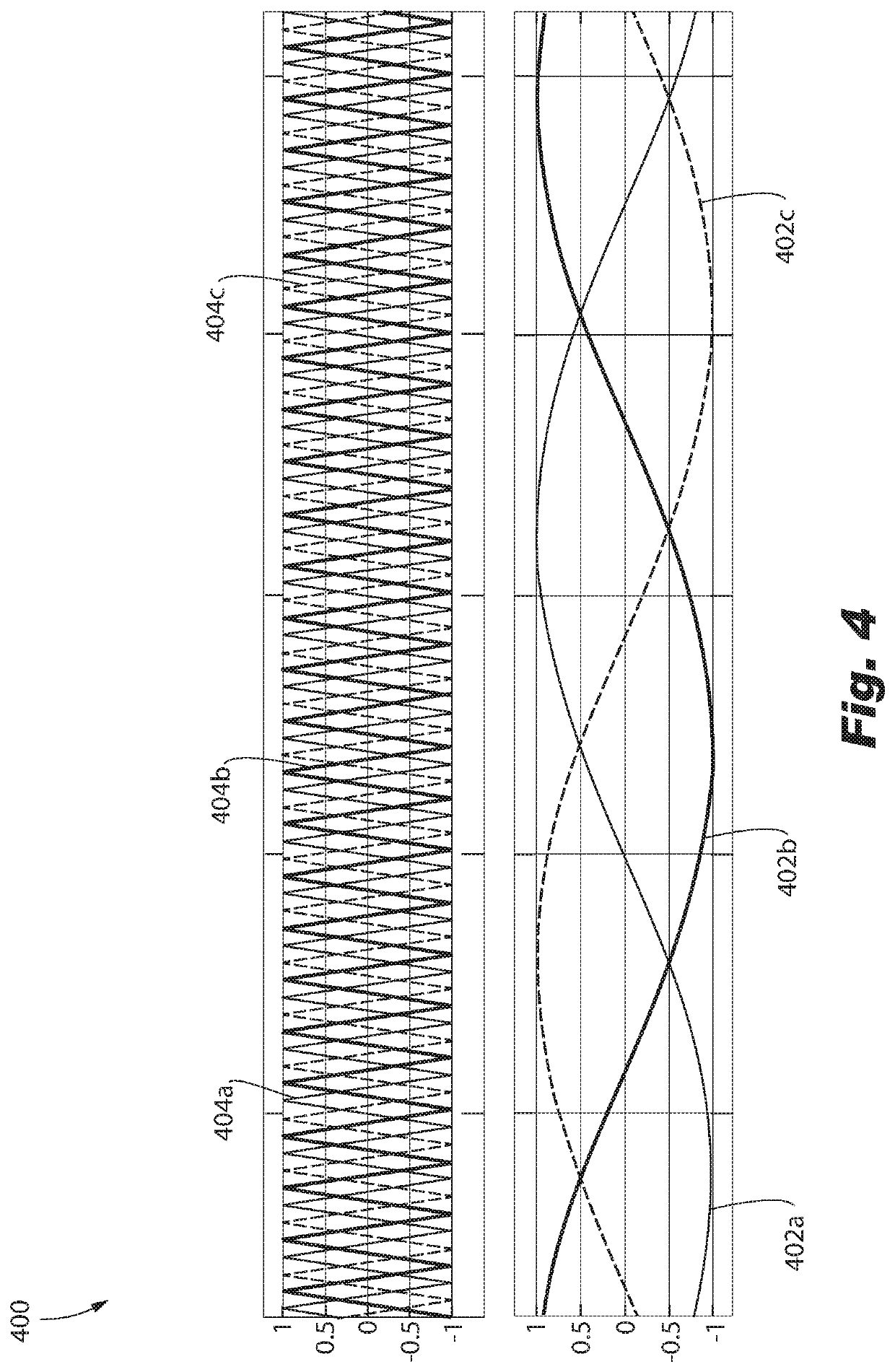
[0015]In one or more embodiments, a core size of a core of each common mode inductor can be reduced by at least about 50% in at least one of size and weight relative to a configuration with a PWM in which all of the signal modulators are configured to receive the same triangle carrier signal.
[0016]In one or more embodiments, a core size of a core of each common mode inductor can be reduced by about 65% in at least one of size and weight relative to a configuration with a PWM in which all of the signal modulators are configured to receive the same triangle carrier signal.
[0024]In accordance with one or more embodiments of the disclosure, the method can further include reducing in at least one of size and weigh by at least about 50% a core size of a core of each common mode inductor filtering the multi-phase signal before it is provided to the motor relative to a configuration in which the same triangle carrier signal is received for each phase power.

Problems solved by technology

This option increases switching losses and burdens a cooling system responsible for cooling the power converter.
In a second option, The converter is provided with multilevel inverters or interleaved inverters, which complicates circuit topology and control of the converter, in addition to the for significantly more semiconductor switches.
However, this option further complicates circuit topology and control of the converter, in addition to the for significantly more semiconductor switches.

Method used


Image

  • Power converter PWM
  • Power converter PWM
  • Power converter PWM

Examples


Embodiment Construction

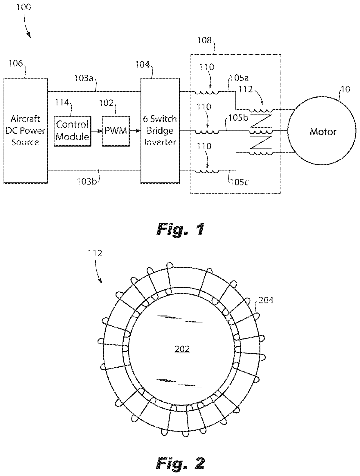
[0035]The illustrated embodiments are now described more fully with reference to the accompanying drawings wherein like reference numerals identify similar structural / functional features. The illustrated embodiments are not limited in any way to what is illustrated, as the illustrated embodiments described below are merely exemplary, which can be embodied in various forms, as appreciated by one skilled in the art. Therefore, it is to be understood that any structural and functional details disclosed herein are not to be interpreted as limiting, but merely as a basis for the claims and as a representation for teaching one skilled in the art to variously employ the discussed embodiments. Furthermore, the terms and phrases used herein are not intended to be limiting but rather to provide an understandable description of the illustrated embodiments.

[0036]Unless defined otherwise, all technical and scientific terms used herein have the same meaning as commonly understood by one of ordina...


PUM


Abstract

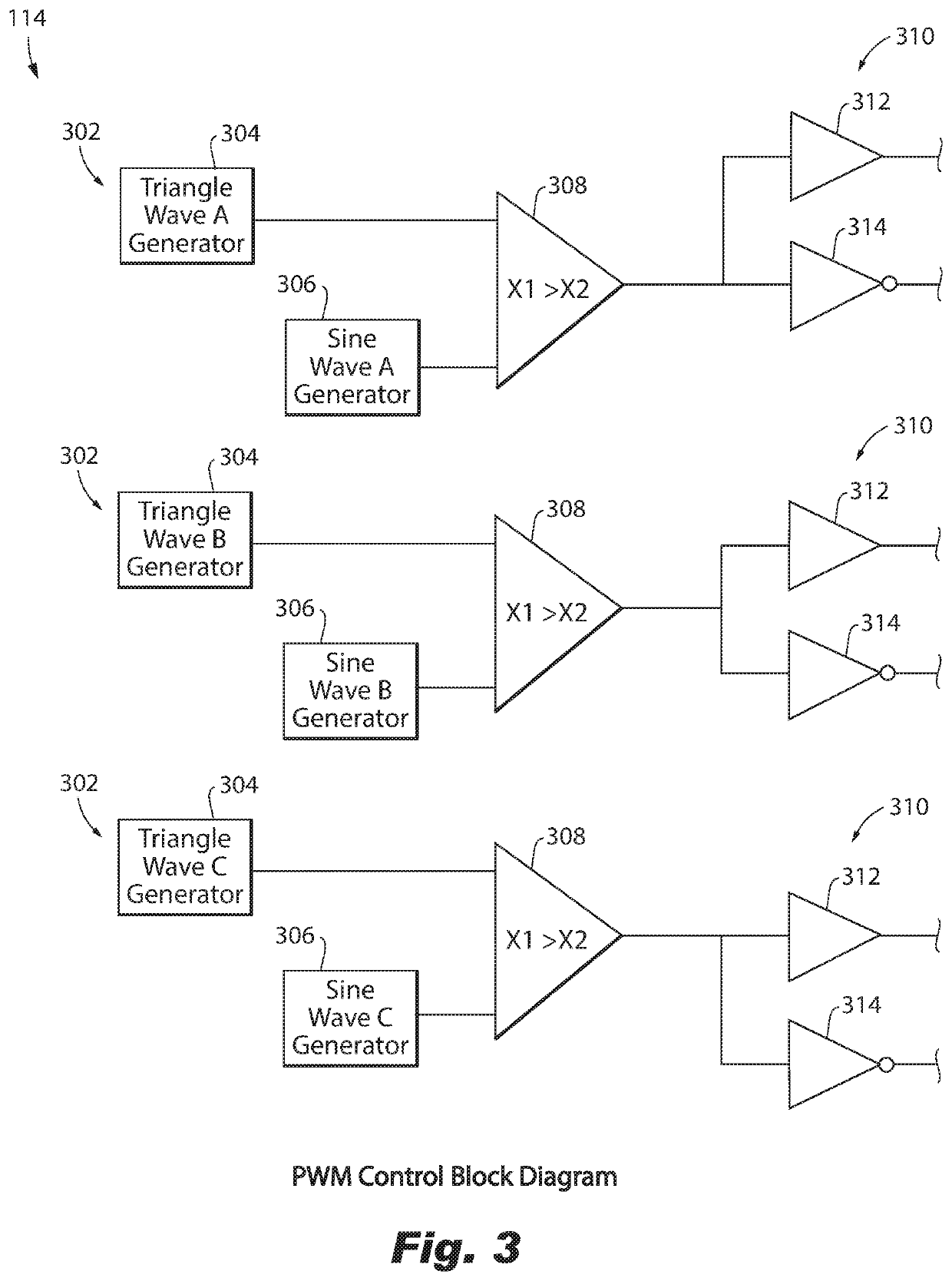
A pulse width modulator (PWM) of a multi-phase power converter is provided. The PWM includes a signal modulator that corresponds to each phase of the converter. Each signal modulator of the PWM is configured to receive a unique triangle carrier signal, receive a unique sine wave signal, compare the received triangle carrier signal and the received sine wave signal, and output at least one control signal based on a result of the comparison. The control signal controls an inverter that applies pulse width modulation to a DC power for converting the DC power to a multi-phase power, AC harmonics of the multi-phase power filtered by a common mode inductor.

Description

BACKGROUND1. Field of the Disclosure[0001]The present disclosure relates to power converters and more particularly, to pulse width modulation controllers of a power converter or aerospace motor controller.2. Description of Related Art[0002]Power converters, including, for example motor controllers, have a filter that uses a common mode inductor. The filter is configured to reduce harmonics generated by switching that occurs within the power converter and to reduce EMI radiation. Ten-thirty percent of the size and weight of the power converter can be attributed to the common mode inductor.[0003]Some options have been traditionally available to reduce the size and / or weight of the common mode inductor of the filter. In a first option, a higher switching frequency is used. This option increases switching losses and burdens a cooling system responsible for cooling the power converter. In a second option, The converter is provided with multilevel inverters or interleaved inverters, which...

Claims


Application Information

Patent Timeline
Patent Type & Authority Patents(United States)
IPC IPC(8): H02P27/08H02M7/5387H02M1/12
CPCH02M7/53871H02M1/126H02P27/08H02M1/44H02M7/5395
Inventor CHAI, HUAZHEN
Owner HAMILTON SUNDSTRAND CORP
Why Eureka
Try Eureka