Power converter, inductance element and inductance cutting control method

A converter and inductance technology, applied in the field of inductance removal control, can solve the problems of poor dynamic performance, decrease in saturation capability, increase in leakage inductance, etc., and achieve the effects of low dynamic inductance, improved saturation capability, and small core volume

Active Publication Date: 2019-11-05
DELTA ELECTRONICS (SHANGHAI) CO LTD
View PDF6 Cites 0 Cited by
  • Summary
  • Abstract
  • Description
  • Claims
  • Application Information

AI Technical Summary

Problems solved by technology

However, conventional anti-coupling inductors have disadvantages such as increased leakage inductance, decreased saturation capability, and poor dynamic performance during light-load phase cut. The motivation of this patent is based on solving these problems of traditional anti-coupling inductors.

Method used


Image

  • Power converter, inductance element and inductance cutting control method
  • Power converter, inductance element and inductance cutting control method
  • Power converter, inductance element and inductance cutting control method

Examples


Embodiment Construction

[0092] Reference will now be made in detail to the exemplary embodiments, examples of which are illustrated in the accompanying drawings. When the following description refers to the accompanying drawings, the same numerals in different drawings refer to the same or similar elements unless otherwise indicated. The implementations described in the following exemplary examples do not represent all implementations consistent with the present disclosure. Rather, they are merely examples of apparatuses and methods consistent with aspects of the present disclosure as recited in the appended claims.

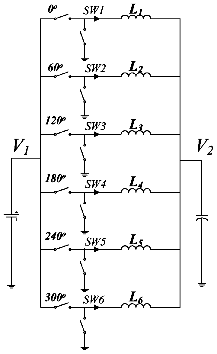
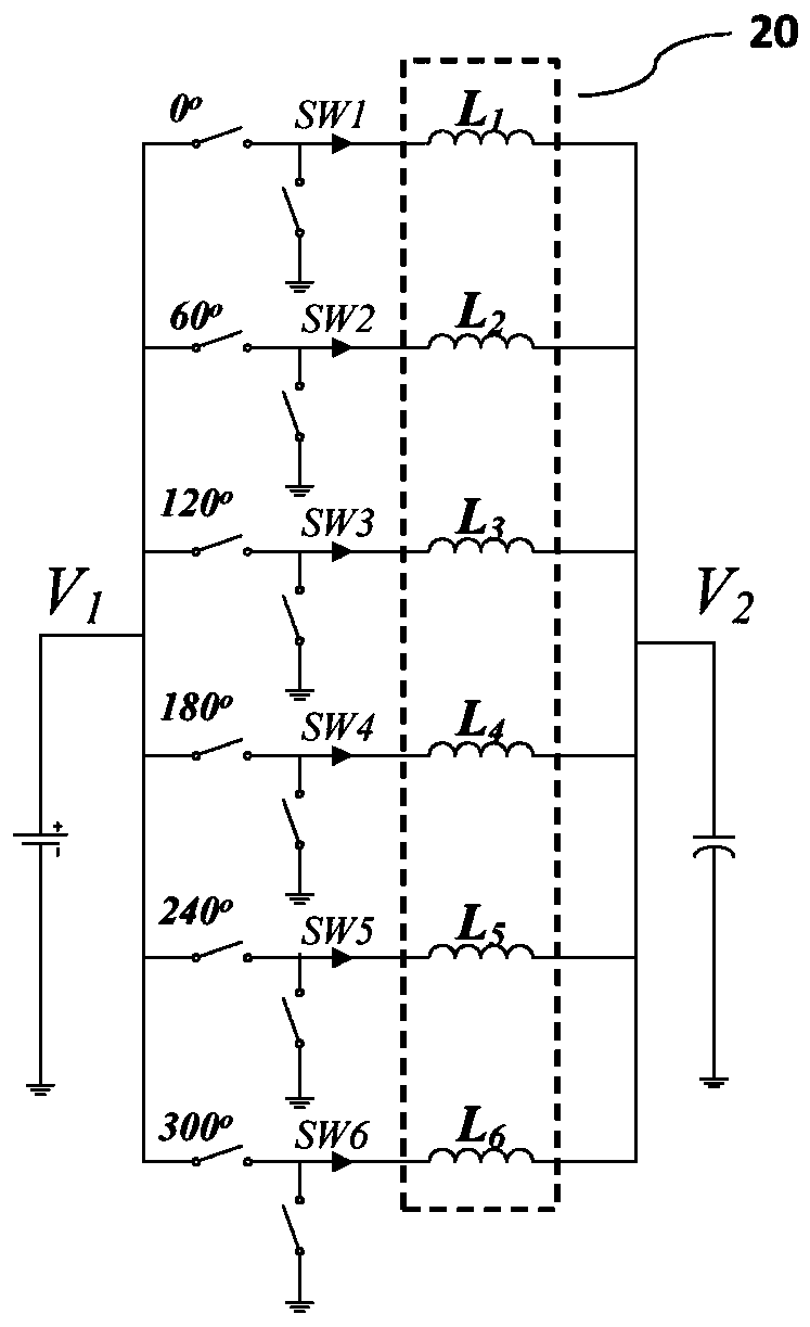
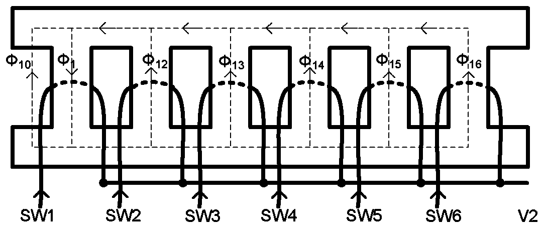
[0093] figure 1 Schematically shows the schematic diagram of the multi-phase parallel DC converter using discrete inductors; figure 2 Schematically shows the schematic diagram of a multi-phase parallel DC converter using anti-coupling inductors; image 3 A typical anti-coupling inductor structure is shown schematically. refer to Figure 1 to Figure 3 , in the field of power conver...


PUM


Abstract

The present disclosure relates to an N-phase power converter, an inductance element, and an inductance cut-off control method, wherein the converter has N phases with parallel inputs and parallel outputs, and the converter includes: N switching units, wherein the N Each phase of the phase power converter includes one of the N switching units; and an integrated inductance unit, the integrated inductance unit includes M inductance subunits, M is a natural number greater than or equal to 2, and each inductance subunit includes i inductances, i is a natural number greater than or equal to 2, and N>M*i or N=M*i, the M*i inductances in the integrated inductance unit are respectively coupled to the inductances in the N switch units M*i switch units, wherein: the i inductances of each inductance subunit are inversely coupled to each other, and the coupling coefficient between the M inductance subunits is smaller than the i in each of the inductance subunits The coupling coefficient between the inductors.

Description

technical field [0001] The present disclosure relates to a power converter, an inductance element, and an inductance cutting control method, and more particularly, relates to a power converter, an inductance element, and an inductor capable of improving the performance of the converter. Excision control method Background technique [0002] In recent years, with the development of data center, artificial intelligence and other technologies, the working speed of central processing unit (CPU), graphics processing unit (GPU) and various integrated chips (IC) is getting faster and faster, and the working current is getting bigger and bigger. , the power density, efficiency, dynamic performance and other aspects of the voltage regulation module (VRM) of its power supply module are becoming more and more stringent, which poses a very high challenge to the design of the VRM. In the voltage regulation module, the volume of the output inductor often accounts for the highest proportio...

Claims


Application Information

Patent Timeline
Patent Type & Authority Patents(China)
IPC IPC(8): H02M3/04H02M1/14
CPCH02M1/14H02M3/04H02M3/1584H01F3/14H01F27/38H01F37/00H02M3/1586H02M3/003Y02B70/10H01F27/24H01F27/28H02M1/0038H02M1/0048H02M1/0064H01F27/306
Inventor 周锦平周敏辛张楠邹莘剑
Owner DELTA ELECTRONICS (SHANGHAI) CO LTD
Why Eureka
Try Eureka