Calibration of an analogue probe

an analogue probe and calibration method technology, applied in the direction of instruments, liquid/fluent solid measurement, mechanical measurement arrangement, etc., can solve the problems of stylus slipping on the sphere surface, assumption becoming invalid, and not always being able to achieve alignmen

Inactive Publication Date: 2005-06-21
RENISHAW PLC
View PDF8 Cites 84 Cited by
  • Summary
  • Abstract
  • Description
  • Claims
  • Application Information

AI Technical Summary

Problems solved by technology

However, such alignment is not always possible to achieve.
However, this assumption becomes invalid when the stylus slips on the surface of the sphere.
There are two factors which can cause the stylus to slip on the sphere surface;i) the machine may not go down the commanded direction accurately enough to prevent slippage,ii) the probe force and deflection vectors may not coincide closely enough to prevent slippage.
Although the sensitivities of the probe axes are acc

Method used


Image

  • Calibration of an analogue probe
  • Calibration of an analogue probe
  • Calibration of an analogue probe

Examples


Embodiment Construction

)

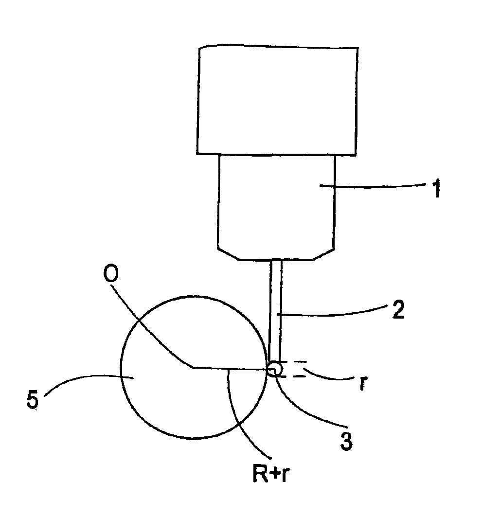
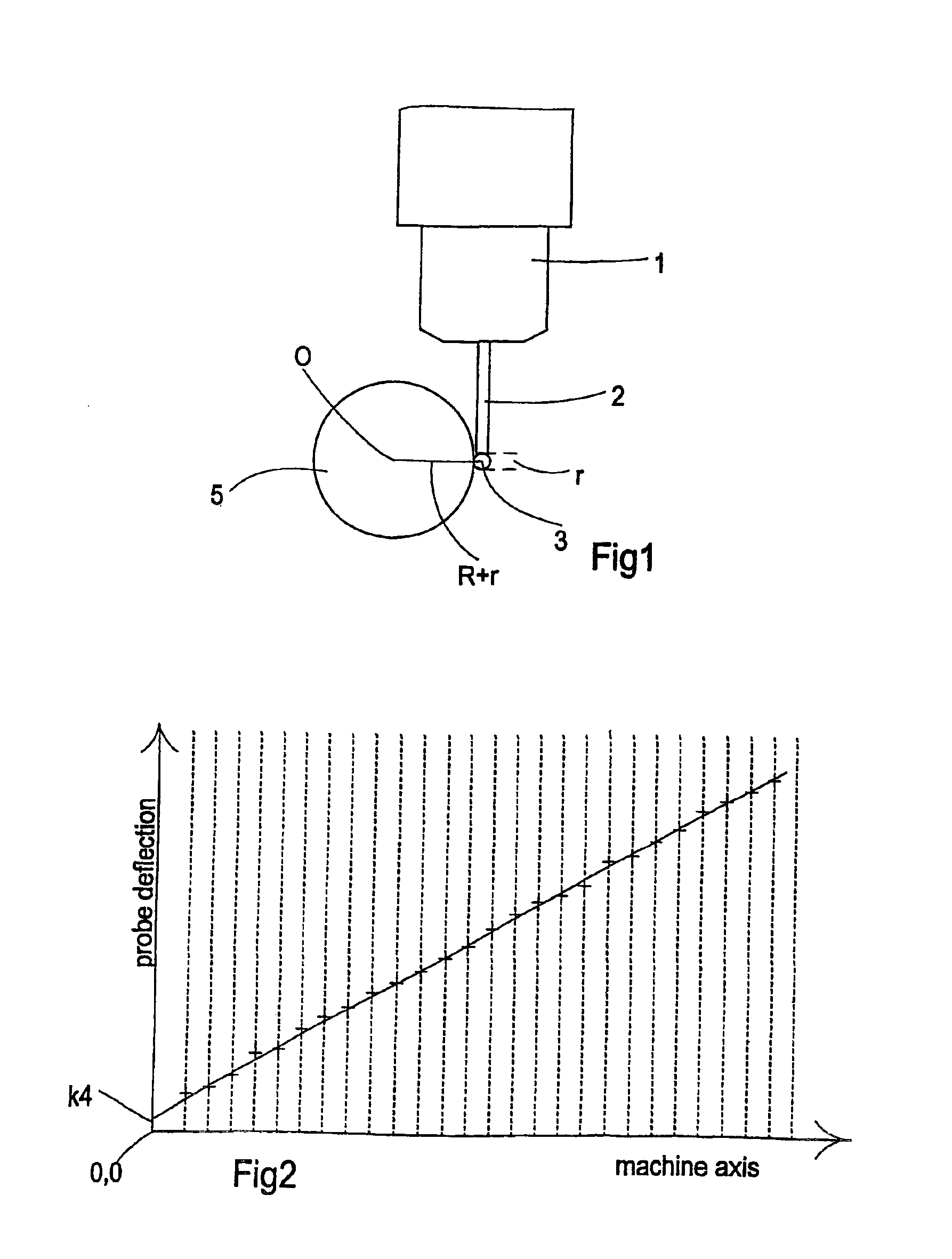
[0029]Referring now to FIGS. 1 and 2, there is shown an analogue probe 1 mounted on a machine quill (not shown) and which has a stylus 2 with a stylus ball 3 at its free end. The stylus is shown in contact with a reference sphere of known radius R and having its centre O at position X1, Y1, Z1 in the machine axis coordinates. The stylus ball has a radius r which is to be determined, along with the position of the centre of the sphere and the probe transformation matrix.

[0030]As a first step in the calibration method the probe must be “zeroed” in its free condition. This simply involves taking readings from the probe measurement transducers when no contact force is acting on the stylus and setting these to zero in all three axes, or alternatively storing these readings so that they can be subtracted from all subsequent readings.

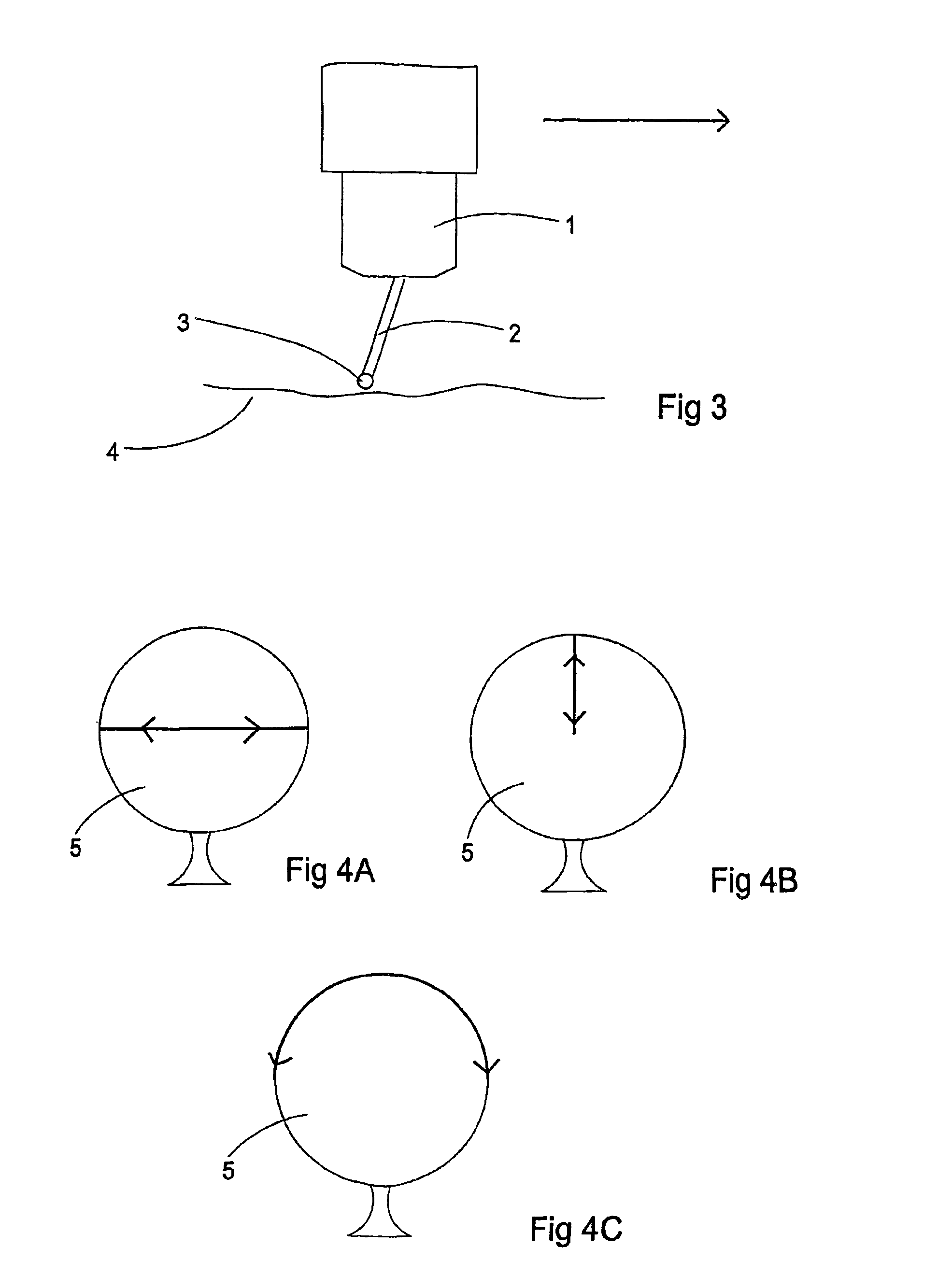
[0031]The next step is to make an estimate of the position of the centre of the sphere, by taking measurements of points at four positions around the surface...


PUM


Abstract

A method of calibrating a probe mounted on a machine in which the probe has a probe calibration matrix which relates the probe outputs in three orthogonal axes to the machine's X, Y and Z coordinate system. A datum ball mounted on the machine is bi-directionally scanned by the probe in one or more planes. For each plane, the mean direction of two approximate probe vectors in the plane is rotated about an axis orthogonal to that plane until the apparent material condition from the scan in each direction is the same. This process may be iterative. The mean values of the directions of the probe vectors for each plane are rotated, thus forming a corrected probe calibration matrix. The datum ball is preferably bi-directionally scanned in three orthogonal planes.

Description

BACKGROUND OF THE INVENTION[0001]1. Field of the Invention[0002]The present invention relates to a method of calibration for analogue probes. The method has particular reference to the calibration of analogue probes which have a stylus for contacting a workpiece, and which is mounted on a mechanical suspension, for example a spring suspension.[0003]2. Description of the Related Art[0004]Analogue probes of this type are well known and an example of such a probe is described in our UK Patent No. 1,551,218. This patent describes a probe suspension mechanism which comprises three orthogonally arranged pairs of parallel springs connected in series between a fixed point on the probe housing and a movable member to which a workpiece contacting stylus is connected.[0005]During a measuring operation on a workpiece using such a probe, a machine on which the probe is mounted is driven towards the workpiece to bring the stylus into contact with the workpiece surface at various points on the sur...

Claims


Application Information

Patent Timeline
IPC IPC(8): G01B21/02G01B21/04G01B21/00G01Q40/02G01Q70/00
CPCG01B21/042B82Y15/00
Inventor SUTHERLAND, ALEXANDER TENNANT
Owner RENISHAW PLC
Why Eureka
Try Eureka