Electronic power unit with a battery and a compensator for calculating the actual charge capacity of the battery

a technology of actual charge capacity and electric power unit, which is applied in the direction of secondary battery servicing/maintenance, liquid/fluent solid measurement, instruments, etc., can solve the problems of inability to accurately compensate the residual capacity, the number of cycles can be easily and accurately counted, and the accuracy of compensating the capacity information is improved. , to achieve the effect of accurate compensation of capacity information, and accurate counting of the number of cycles

Inactive Publication Date: 2005-06-21
LENOVO PC INT
View PDF4 Cites 13 Cited by
  • Summary
  • Abstract
  • Description
  • Claims
  • Application Information

AI Technical Summary

Benefits of technology

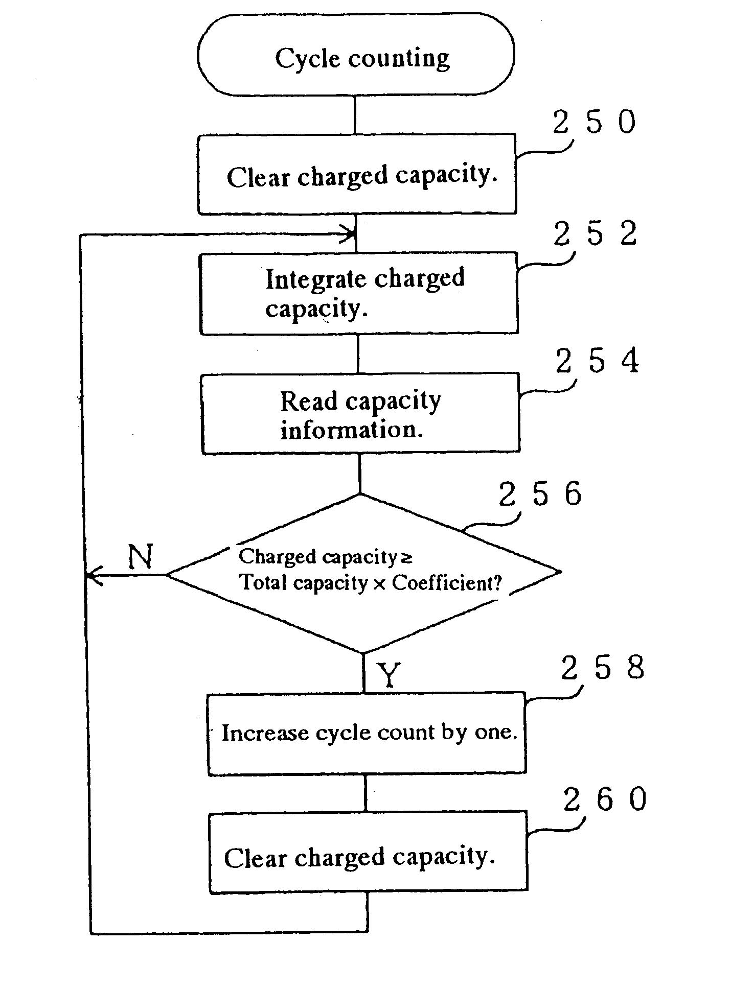
[0016]Because the electric power unit of the present invention stores the compensation information that denotes the total capacity of the battery with respect to the cycle count and compensates the capacity information denoting the total capacity of the battery, it is possible to compensate the capacity information accurately according to the cycle count of the battery with use of the compensation information even when the battery capacity never reaches zero nor a predetermined capacity near zero.
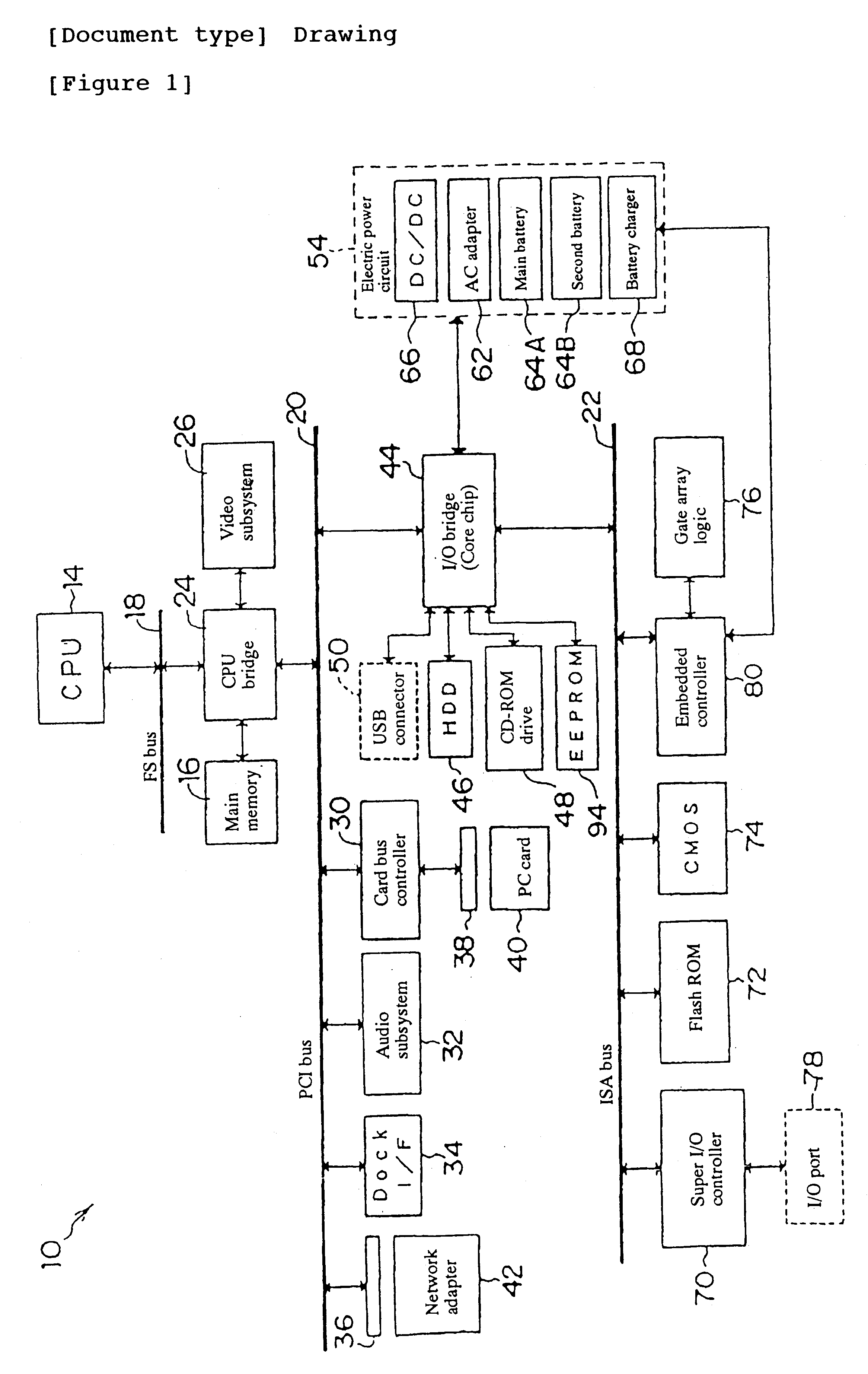
[0035]Furthermore, in case the electric power capacity information compensating method of the present invention is employed for a computer provided with components including a CPU, a storage device, a display device, an input device, a network connection device, and an electric power unit that stores capacity information denoting the total capacity of the built-in battery so that all those components are connected to each another via a bus respectively, an external storage device of a server computer disposed on a network to which the network connection device is connected may be a recording medium that stores a program for compensating the capacity information stored in the electric power unit in accordance with the electric power capacity information compensating method of the present invention so as to be read from the computer. This computer can thus compensate the capacity information of the electric power unit accurately.

Problems solved by technology

However, the above technique for enabling the battery to learn the capacity information when the capacity reaches zero or a predetermined capacity near zero does not always work; in which case, the accuracy of the residual capacity cannot be improved.
This problem arises due to the following two reasons.
First, it is generally very rare that a second battery is discharged completely before it is recharged.
And, in case such the cyclical operation is continued, the battery never learns the capacity information.
Consequently, the battery is never used until its capacity reaches zero in any actual use, so that the battery does not learn the capacity information.
In case the user begins using the battery in such a state, the battery might cause a residual capacity skip error (for example, the residual capacity is reduced to 10% abruptly from 50%).
In this case, the user will judge the battery abnormal, so the maker is often forced to replace the battery.

Method used


Image

  • Electronic power unit with a battery and a compensator for calculating the actual charge capacity of the battery
  • Electronic power unit with a battery and a compensator for calculating the actual charge capacity of the battery
  • Electronic power unit with a battery and a compensator for calculating the actual charge capacity of the battery

Examples


first embodiment

[0070]FIG. 3 shows a block diagram of the main battery 64A with respect to the connection between the main battery 64A and each of other components. As shown in FIG. 3, the main battery 64A in the first embodiment is configured by a CPU 102 that controls the operation of the whole main battery 64A; a memory 104 that stores various data items; a battery 106 configured by three lithium-ion batteries of a 4.2V rating voltage disposed serially; a resistor 108 that detects the charged and discharged capacities of the battery 106; and four external terminals T1 to T4. The memory 104 may be a rewritable non-volatile memory such as an EPROM, an EEPROM, a flash EEPROM, or the like.

[0071]One electrode of the battery 106 is connected to an external terminal T1 and the other electrode of the battery 106 is connected to an external terminal T3 via the resistor 108. And, the CPU 102 is connected to the memory 104, so that the CPU 102 can write / read various data to / from the memory 104. The CPU 102...

second embodiment

[0106]FIG. 7 shows a block diagram of a main battery 64A′ in this second embodiment and the connection between the main battery 64A′ and each of other components. In FIG. 7, the same symbols will be given to the same components as those shown in FIG. 3, avoiding redundant description.

[0107]As shown in FIG. 7, the main battery 64A′ in the second embodiment are the same as the main battery 64A in the first embodiment except that the battery 64A′ is not provided with any of the CPU 102 and the resistor 108, and the memory 104′ is directly connected to the external terminals T2 and T4.

[0108]The external terminal T1 of the main battery 64A′ configured as described above is connected to an input terminal of a DC / DC converter 66 via a resistor 110 used to detect the charged / discharged capacity of the battery 106 in the internal circuit 120′ of the PC 12. The DC / DC converter 66 receives an electric power from the battery 106 via the main battery 64A′. Both terminals of the resistor 110 are ...


PUM

PropertyMeasurementUnit
temperaturesaaaaaaaaaa
rated voltageaaaaaaaaaa

Abstract

A main battery used as an electric power unit for a computer is provided with a memory that stores capacity information denoting the total capacity of a battery and compensation information representing the total capacity of the battery as a function of a battery charging cycle count. A CPU detects a cycle count of the battery according to an integrated charged capacity of the battery, thereby obtaining the total capacity with respect to this cycle count from the compensation information so as to compensate the capacity information according to the obtained total capacity.

Description

FIELD OF THE INVENTION[0001]The present invention relates generally to an electric power unit, an electric power capacity information compensator, an electric power capacity information compensating method, and a computer, more particularly to an electric power unit provided with a battery enabled to supply an electric power, an electric power capacity information compensator and an electric power capacity information compensating method for compensating capacity information denoting the total capacity of a battery built in the electric power unit, and a computer that employs the electric power capacity information compensating method.BACKGROUND OF THE INVENTION[0002]In recent years, there have appeared portable personal computers (hereinafter referred to as portable PCs) developed in various sizes and provided with various functions so as to cope with the spread of mobile computing. For example, there are lap-top personal computers, more compact lap-top personal computers, palm-top...

Claims


Application Information

Patent Timeline
Patent Type & Authority Patents(United States)
IPC IPC(8): G06F1/28G06F1/26G06F1/20H01M10/42
CPCG06F1/28G06F1/26
Inventor ODAOHHARA, SHIGEFUMITSURUKAWA, NOBORU
Owner LENOVO PC INT
Why Eureka
Try Eureka