
Memory-module burn-in system with removable pattern-generator boards separated from heat chamber by backplane

a memory module and backplane technology, applied in the field of environmental test systems, can solve the problems of poor solder connection on the board or module, failure to meet the requirements of the test,

Active Publication Date: 2005-06-21
KINGSTON DIGITAL CO LTD
View PDF19 Cites 32 Cited by
  • Summary
  • Abstract
  • Description
  • Claims
  • Application Information

AI Technical Summary

Problems solved by technology

Weak components often fail earlier at elevated temperatures that at normal temperatures.
Poor solder connections on boards or modules can break at higher temperatures, and thermal expansion can loosen poorly seated components.
Other manufacturing defects that do not cause immediate failures can create failures that appear after many hours of normal operation at normal temperatures, or after just a few hours at elevated temperatures.
The memory-module industry is quite cost sensitive.
Testing costs are significant, especially for higher-density modules.
Specialized, high-speed electronic test equipment is expensive, and the greater number of memory cells on high-speed memory modules increases the time spent on the tester, increasing test costs.
Burn-in testing can be quite expensive, as each module may have to remain at an elevated temperature in a specialized burn-in tester for many hours or even days.
Exercising the memory modules at higher frequencies is difficult, especially when the modules are within a burn-in oven or heated test chamber.
Cables or wires that connect an external test-pattern generator or other test equipment to the memory modules within the oven can be long, severely limiting the frequency of operation.

Method used


Image

  • Memory-module burn-in system with removable pattern-generator boards separated from heat chamber by backplane
  • Memory-module burn-in system with removable pattern-generator boards separated from heat chamber by backplane
  • Memory-module burn-in system with removable pattern-generator boards separated from heat chamber by backplane

Examples


Embodiment Construction

[0014]The present invention relates to an improvement in memory-module testers. The following description is presented to enable one of ordinary skill in the art to make and use the invention as provided in the context of a particular application and its requirements. Various modifications to the preferred embodiment will be apparent to those with skill in the art, and the general principles defined herein may be applied to other embodiments. Therefore, the present invention is not intended to be limited to the particular embodiments shown and described, but is to be accorded the widest scope consistent with the principles and novel features herein disclosed.

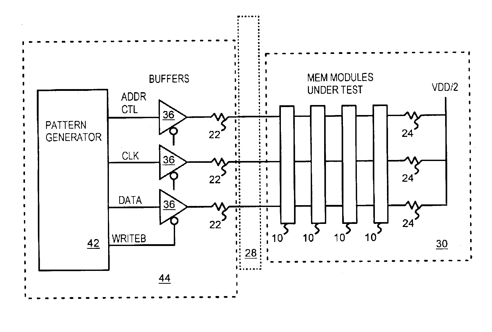
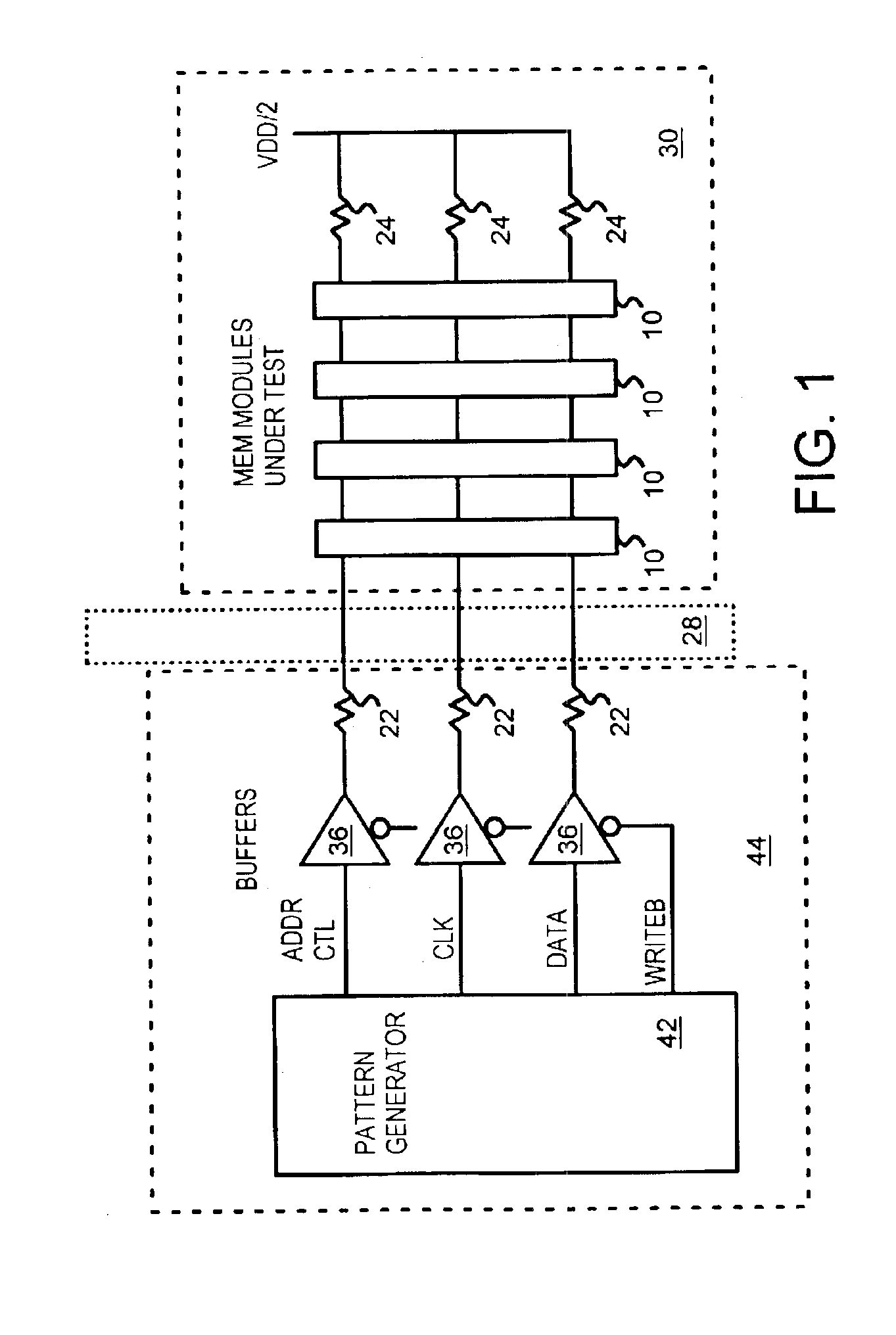
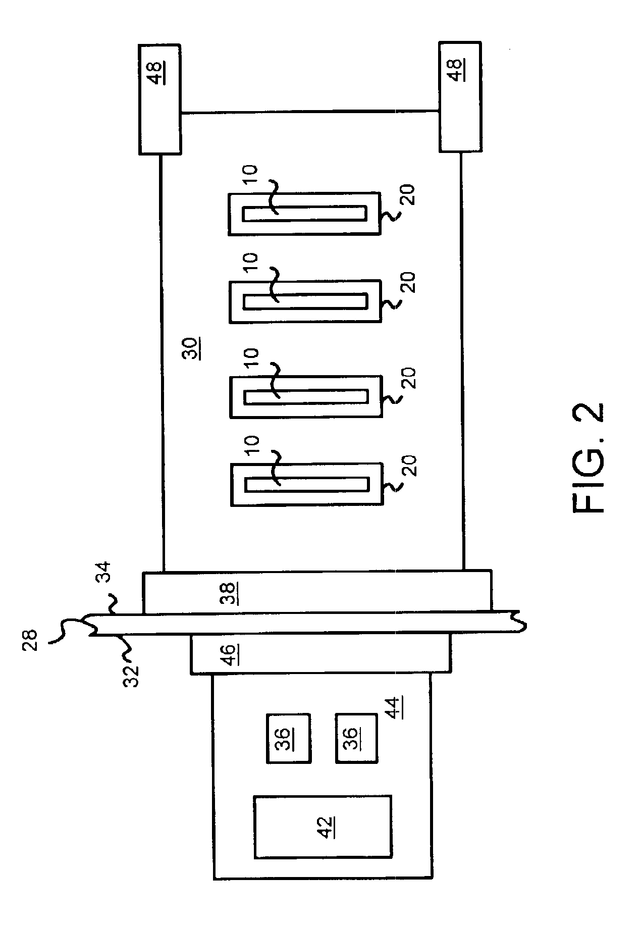
[0015]FIG. 1 is an electrical block diagram of a burn-in tester of memory modules. Backplane 28 separates pattern-generator card 44 from module motherboard 30. A socket (not shown) on the back side of backplane 28 receives an edge of pattern-generator card 44 while a socket (not shown) on the front side of backplane 28 receives ...


PUM


Abstract

An environmental tester for memory modules has an environmental chamber for heating the memory modules being tested. One side of the chamber is a backplane. The memory modules are inserted into sockets on module motherboards, which are inserted into motherboard sockets on the backplane. On the other side of the backplane, card sockets receive pattern-generator cards that are outside the environmental chamber but electrically connected to the module motherboards through the backplane. The pattern-generator cards contain pattern-generators that generate address, data, and control signals that exercise the memory modules. The pattern-generator cards can be cooled while the memory modules in the environmental chamber are heated. Pattern-generator cards can be removed for repair and module motherboards can be removed for inserting new memory modules for testing.

Description

BACKGROUND OF INVENTION[0001]This invention relates to environmental test systems, and more particularly to memory module burn-in testers.[0002]High-availability and critical systems such as web or transaction servers required the use of enhanced-reliability components. Additional testing can be performed on components such as board assemblies, semiconductor chips, and memory modules. Often this additional testing is often performed at an elevated temperature. Thus environmental testing is sometimes known as burn-in.[0003]Weak components often fail earlier at elevated temperatures that at normal temperatures. Poor solder connections on boards or modules can break at higher temperatures, and thermal expansion can loosen poorly seated components. Other manufacturing defects that do not cause immediate failures can create failures that appear after many hours of normal operation at normal temperatures, or after just a few hours at elevated temperatures. Thus elevated-temperature testin...

Claims


Application Information

Patent Timeline
IPC IPC(8): G01R31/28G11C29/56G01R31/319
CPCG11C29/56004G11C29/56016G11C29/56G01R31/2863G01R31/31905G11C2029/2602
Inventor CO, RAMON S.LAI, TAT LEUNGSUN, DAVID DA-WEI
Owner KINGSTON DIGITAL CO LTD
Learn More