Vortex flow sensor for measuring fluid flow through a flow tube

a flow sensor and flow tube technology, applied in the direction of volume/mass flow by dynamic fluid flow effect, indirect mass flowmeter, liquid/fluent solid measurement, etc., can solve the problems of narrowing the application range of vortex flow sensors, reducing the attractiveness of the market, and not being resistant to all fluids, etc., to achieve improved fluid temperature measurement and high thermal conductivity

Inactive Publication Date: 2005-06-28
ENDRESS HAUSER FLOWTEC AG
View PDF7 Cites 62 Cited by
  • Summary
  • Abstract
  • Description
  • Claims
  • Application Information

AI Technical Summary

Benefits of technology

[0026]One advantage of the invention is that the temperature sensors cannot come into contact with the flowing fluid, and thus cannot be corroded by the fluid. Still, the temperature sensors are located so close to the fluid that they measure its temperature practically instantaneously, particularly at different measurement points; they are separated from the fluid only by the thin wall of the vortex sensing element or of the bluff body, and these parts, like the other parts of the vortex flow

Problems solved by technology

This temperature sensor, too, is passed over by the flowing fluid and, as the inventors have found, is not resistant to all fluids occurring in operation, i.e., some fluids corrode temperature sensors arra

Method used


Image

  • Vortex flow sensor for measuring fluid flow through a flow tube
  • Vortex flow sensor for measuring fluid flow through a flow tube
  • Vortex flow sensor for measuring fluid flow through a flow tube

Examples


Embodiment Construction

[0034]While the invention is susceptible to various modifications and alternative forms, exemplary embodiments thereof have been shown by way of example in the drawings and will herein be described in detail. It should be understood, however, that there is no intent to limit the invention to the the particular forms diclosed, but on the contrary, the intention is to cover all modifications, equivalents, and alternatives falling within the spirit and scope of the invention as defined by the intended claims.

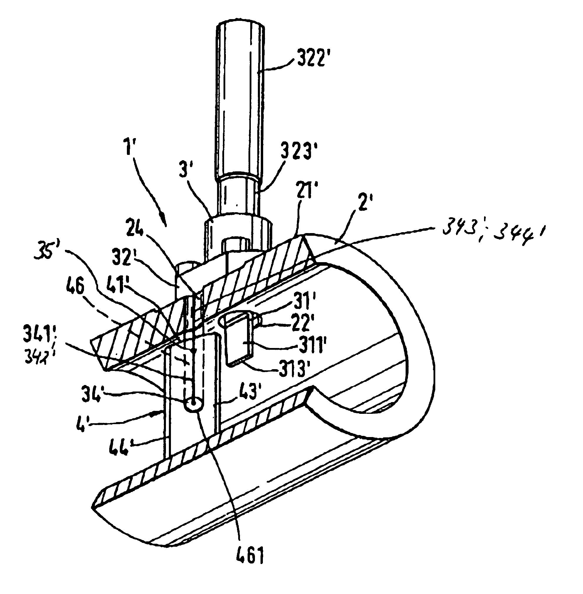
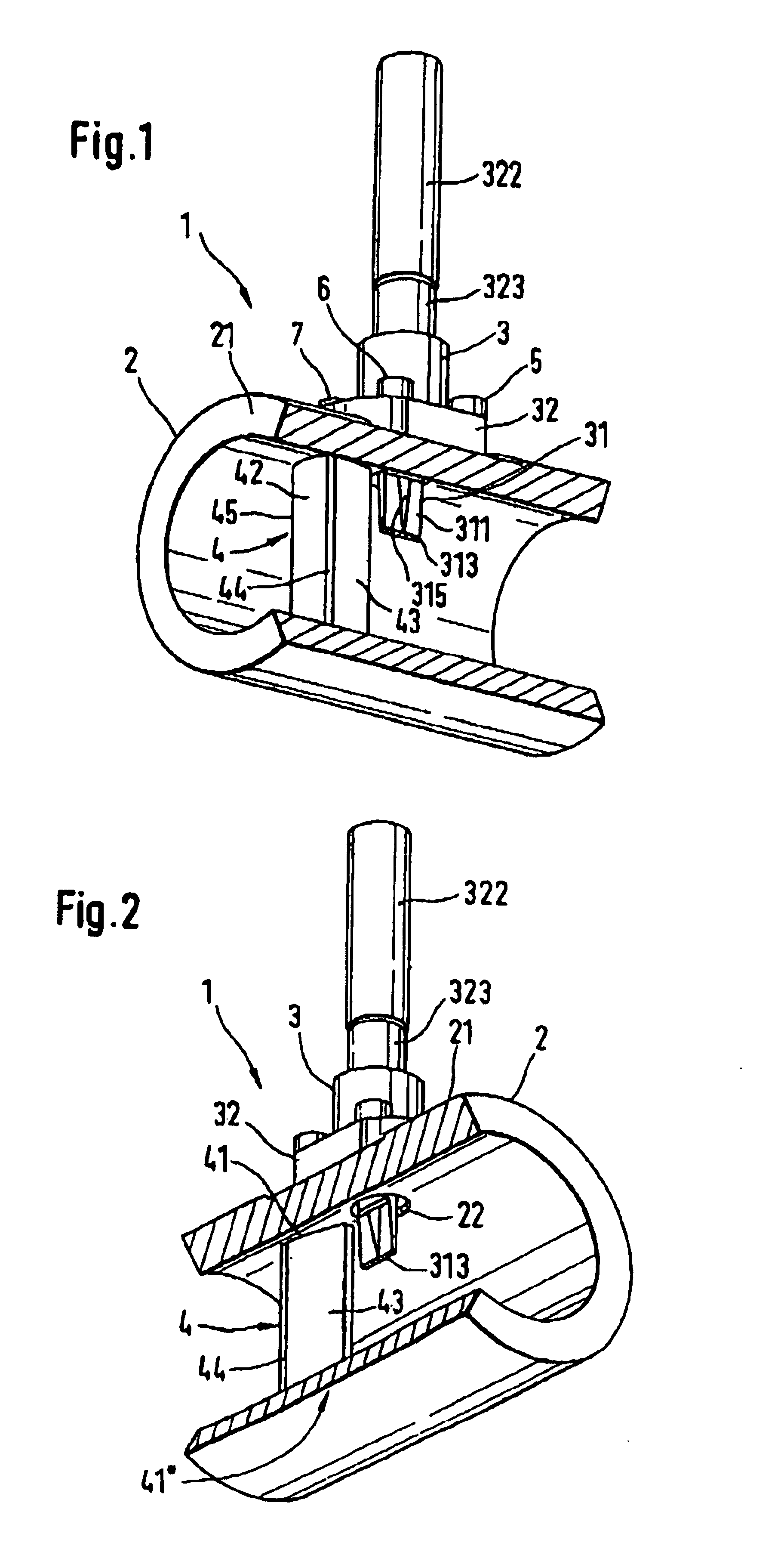
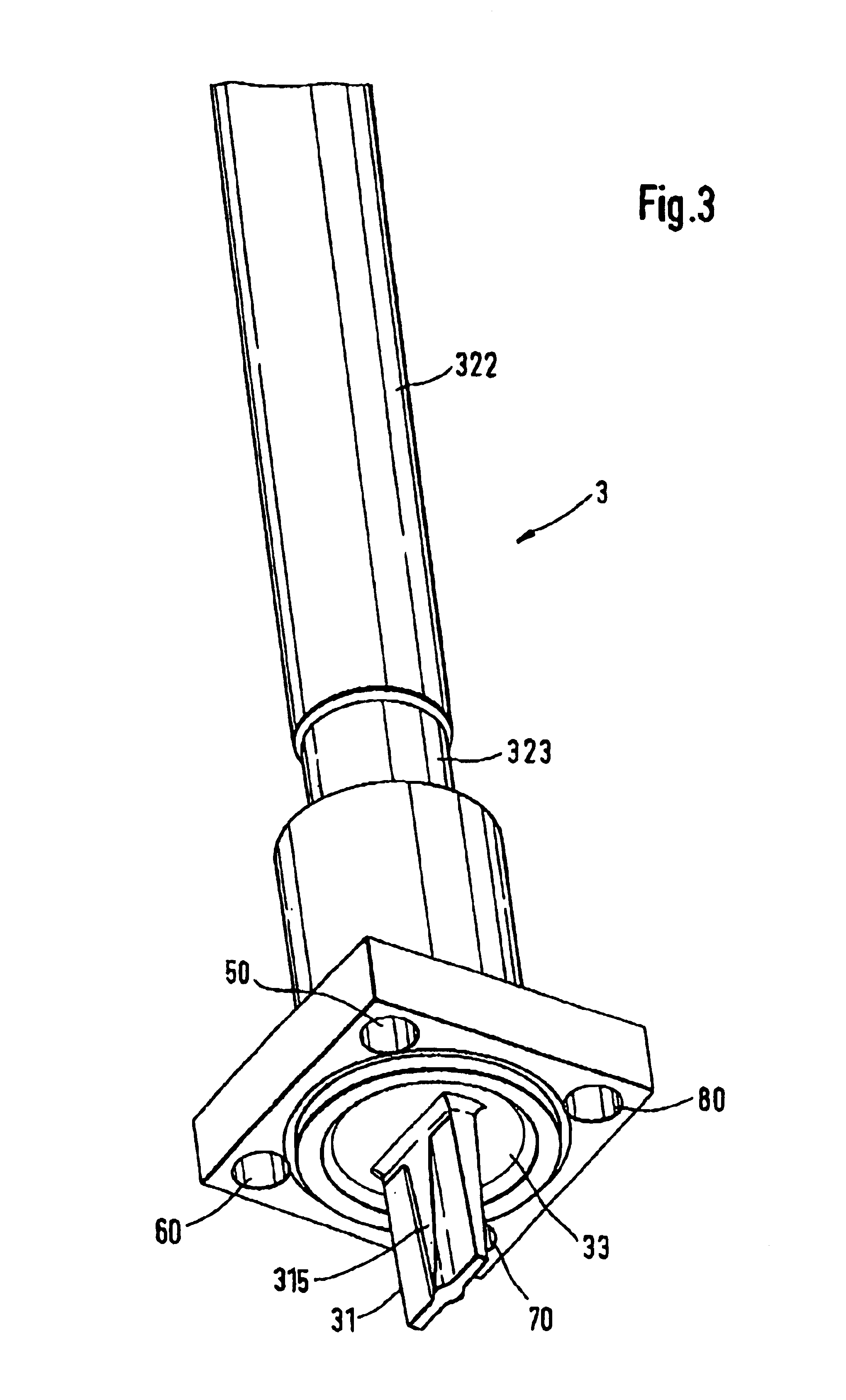
[0035]FIGS. 1 to 4 will be described together, because it is not possible to represent all details in every figure. The perspective views of an embodiment of the first variant, which are shown in FIGS. 1 and 2 and serve to provide an overall view, show a cut-away vortex flow sensor 1 as viewed in the direction of fluid flow (FIG. 1) and in the opposite direction (FIG. 2), which comprises a vortex sensor device 3 which is fixed to a wall 21 of a flow tube 2 and extends through a hol...


PUM


Abstract

The vortex flow sensor is designed to measure the mass flow rate, the volumetric flow rate, or the flow velocity of a fluid flowing in a flow tube having a tube wall, and has two temperature sensors arranged in such a way that the vortex flow sensor may also be used with fluids which would corrode the temperature sensors. A bluff body in the flow tube sheds vortices and thus causes pressure fluctuations. A vortex sensor device responsive thereto is fitted downstream of the bluff body in a hole provided in the wall of the flow tube. The vortex sensor device comprises a sensor vane extending into the fluid. The temperature sensors are disposed in a blind hole of the sensor vane. Alternatively, the temperature sensor may be disposed in blind hole of the bluff body.

Description

[0001]This application is based on Provisional Application No. 60 / 422,867, filed Nov. 1, 2002.[0002]This application is also a continuation-in-part of prior application Ser. No. 10 / 233,673, filed Sep. 4, 2002.FIELD OF THE INVENTION[0003]This invention relates to a vortex flow sensor for measuring the volumetric flow rate, the mass flow rate, or the flow velocity of a fluid flowing through a flow tube, i.e. liquid, vapor or gas, the vortex flow sensor comprising a bluff body disposed in a lumen of the flow tube and serving to shed Kármán vortices.BACKGROUND OF THE INVENTION[0004]The volumetric flow rate and the mass flow rate are defined as the volume and the mass, respectively, of the fluid that passes through the cross section of the flow tube in a unit time. During operation of such a vortex flow sensor, a Kármán vortex street is, as is known, formed downstream of the bluff body, and the pressure fluctuations of this vortex street are converted by a vortex sensor device into an el...

Claims


Application Information

Patent Timeline
IPC IPC(8): G01F1/32G01F1/86G01F1/76
CPCG01F1/3209G01F1/3218G01F1/86G01F1/3272G01F1/3263G01F1/3273G01F1/3266
Inventor KOUDAL, OLENIERLICH, THOMASHOCKER, RAINER
Owner ENDRESS HAUSER FLOWTEC AG
Why Eureka
Try Eureka