Chromatograph valve and method of use

a chromatograph valve and valve body technology, applied in the field of valves, can solve the problems of non-uniform sample sizes, affecting the uniformity of sample sizes, and affecting the final concentration calculation, and achieve the effects of minimizing dead volume, minimizing the chance of volatilized samples condense, and minimizing the chance of pre-volatilization of sample materials

Inactive Publication Date: 2005-06-28
KRIEL WAYNE A
View PDF8 Cites 22 Cited by
  • Summary
  • Abstract
  • Description
  • Claims
  • Application Information

AI Technical Summary

Benefits of technology

[0010]The present invention avoids the necessity of enclosing the valve body in an oven with the attendant complications of thermocouples and temperature measurement circuitry to control the heat. The present invention also avoids the need for heater collars which have been used historically to surround, the valve body to heat and vaporize the sample.
[0011]The present invention is an improvement over existing valves because the distance between the GC inlet and the port where a measured sample leaves the valve is minimized while at the same time the distance between that port and a port where sample material enters the valve is maximized. The small distance between the GC inlet and the port where a measured sample leaves the valve, which minimizes dead volume, also minimizes the chances for a volatilized sample to condense. The large distance between the port where a measured sample leaves the valve and the port where sample material enters the valve minimizes the chances for pre-volatilization of sample material.

Problems solved by technology

Non uniform sample size directly affects final concentration calculations.
Wear within the valve body can affect the precision machined slots and passages in the valve which carry the measured sample, thus, affecting the uniformity of sample size.
The volume of a partially volatilized sample varies from a non-volatilized sample, thus, pre-volatilization creates non-uniform sample sizes.
Condensation can prevent the separating column from functioning correctly for the sample material being analyzed and condensed material may remain in the column, sample inlet and / or transfer lines rendering future measurements inaccurate as well.

Method used


Image

  • Chromatograph valve and method of use
  • Chromatograph valve and method of use
  • Chromatograph valve and method of use

Examples


Embodiment Construction

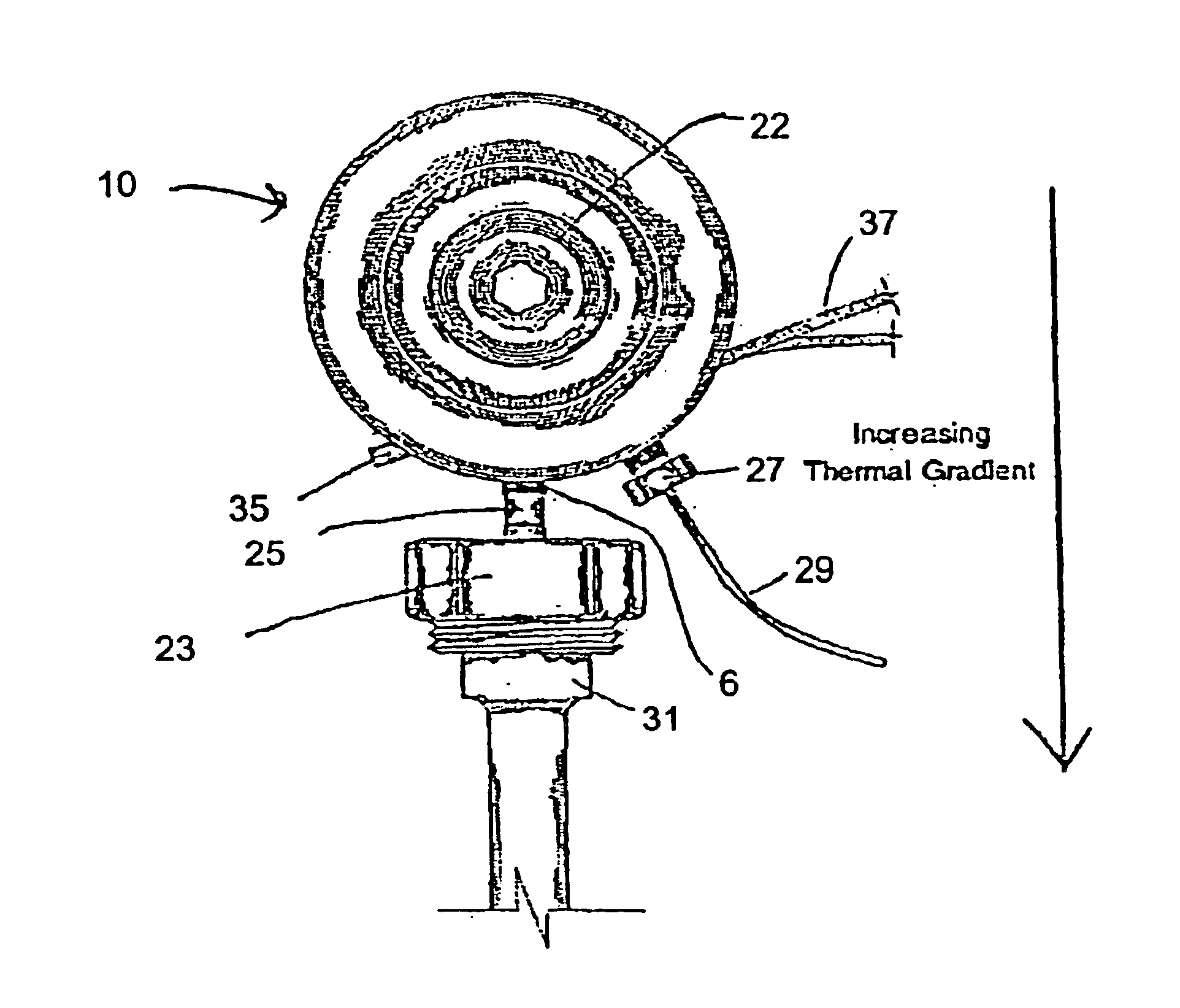
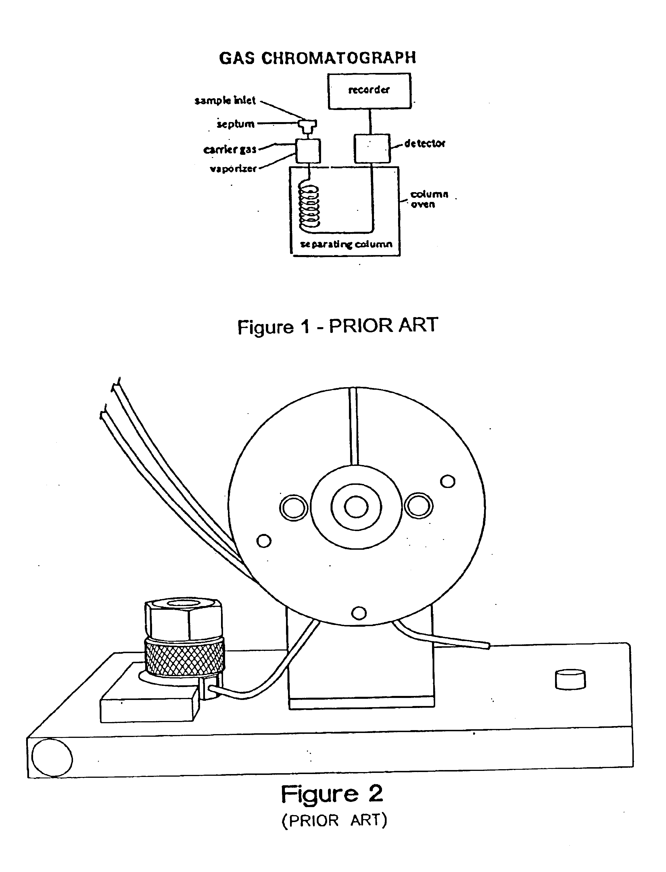
[0022]The present invention relates to a new valve for a gas chromatograph (GC) which is mounted proximally adjacent the GC inlet. In prior art devices as shown in FIG. 2, the valve selectively moved a sample into the carrier gas stream for analysis through a port and tubing that was thermally isolated from the GC inlet. The present invention allows the valve to be placed in close proximity to the GC inlet (i.e. not thermally isolated). As a result the present invention provides temperature control of the sample within the valve and within the space between the valve and GC inlet.

[0023]Valve Body—General

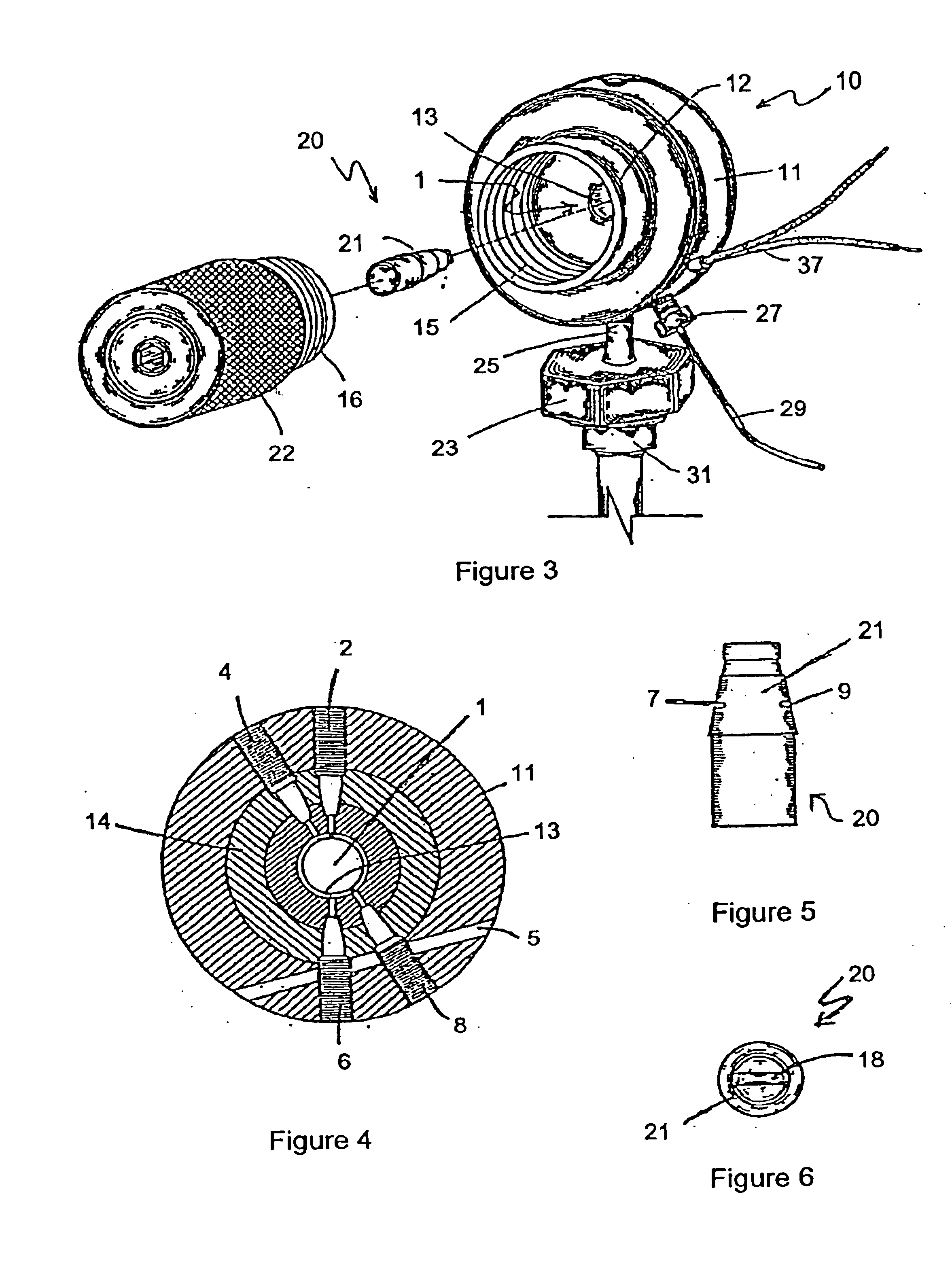
[0024]FIG. 3 discloses the valve of the present invention. Valve body 10 is fashioned from stainless steel but can be formed by any non-reactive metal appropriate under the circumstances of its intended use. Valve body 10 may be machined from an integral stainless steel blank having a substantially round exterior portion 11 although the exterior portion 11 may be any shape including ...


PUM

PropertyMeasurementUnit
volumeaaaaaaaaaa
tensionaaaaaaaaaa
temperatureaaaaaaaaaa

Abstract

An improved chromatograph valve is provided which may be placed in close proximity to a chromatograph in order to avoid temperature variations in the space therebetween. The valve may include a multiple sample slot rotor movable in a single direction to reduce wear upon the rotor and valve body. The rotor sample slots as well as the pairs of sample and carrier gas ports upon the valve body may be diametrically opposed to allow a superior temperature gradient to be created across the valve, the gradient allowing a sample material to enter the valve in a single phase and exit the valve sufficiently volatilized.

Description

PRIORITY CLAIM[0001]This application claims the benefit of U.S. provisional patent application No. 60 / 294,725 filed on May 31, 2001 the entirety of which is hereby incorporated by reference.FIELD OF INVENTION[0002]The present invention relates to a valve adapted for use with a chromatograph, specifically, to a valve providing direct entry to the chromatograph without auxiliary prevolatilization heating or post-injection cooling of the sample.BACKGROUND OF THE INVENTION[0003]In the field of chemical analysis, the gas chromatograph (GC) has been a mainstay of chemists since the early 1950's. The basic gas chromatograph as shown in FIG. 1 includes four functional units: an inlet for sample material, a carrier gas supply, a separating column, and a detector for sensing the composition of the column effluent. A measured sample is introduced through the sample inlet and vaporized within the carrier gas prior to entry into the separating column. The sample inlet may include a septum or oth...

Claims


Application Information

Patent Timeline
Patent Type & Authority Patents(United States)
IPC IPC(8): G01N30/00G01N30/30G01N30/20G01N30/12
CPCG01N30/20G01N30/30G01N2030/3046G01N2030/3015G01N2030/127
Inventor KRIEL, WAYNE A.
Owner KRIEL WAYNE A
Why Eureka
Try Eureka