Apparatus for attaching a sensor to a tubing string

a technology a tubing string, which is applied in the field of methods and apparatus for attaching a sensor to a tubing string, can solve the problems of not having enough force to push the string away from the casing, data acquisition conditions are less than ideal, and both spring and arm systems are facing challenges

Inactive Publication Date: 2005-06-28
HALLIBURTON ENERGY SERVICES INC
View PDF33 Cites 31 Cited by
  • Summary
  • Abstract
  • Description
  • Claims
  • Application Information

AI Technical Summary

Benefits of technology

[0014]The first clamping portion also provides access to connect a sensor to adjacent sensors in a sensor array. In alternative embodiments, either the first or second portion inside diameter may have one or more gripping dogs to ensure the attachment to the tubing string. The clamp assembly may also have one or more bypass grooves to allow for tubing and / or cabling from adjacent instrumentation packages to bypass the clamping assembly.
[0015]The present invention may also be embodied as a method for disposing a sensor in a highly deviated or horizontal wellbore. A sensor is placed inside a first clamping portion that is combined with a second clamping portion and compressed against a tubing string using a predetermined force. Once the predetermined force is reached, attachment members are installed attaching the first portion to the second portion. Sensor and clamping assembly is then lowered into the wellbore where, in a highly deviated or horizontal section, the tubing and clamp assembly will come to rest on one side of the casing.

Problems solved by technology

When operating in highly deviated well sections, including near horizontal and horizontal sections, both spring and arm systems have faced challenges.
Although most spring and arm systems are designed to actuate with a force greater than the weight of the sensor, they may not have enough force to push the string away from the casing, when the sensor is between the casing and the tubing, or sufficient reach to push the sensor against the far wall of the casing, when the tubing is directly against the casing.
If the system fails to fully actuate, the sensor may not be maintained in the desired, stable relationship with the wellbore, making data acquisition conditions less than ideal.

Method used


Image

  • Apparatus for attaching a sensor to a tubing string
  • Apparatus for attaching a sensor to a tubing string
  • Apparatus for attaching a sensor to a tubing string

Examples


Embodiment Construction

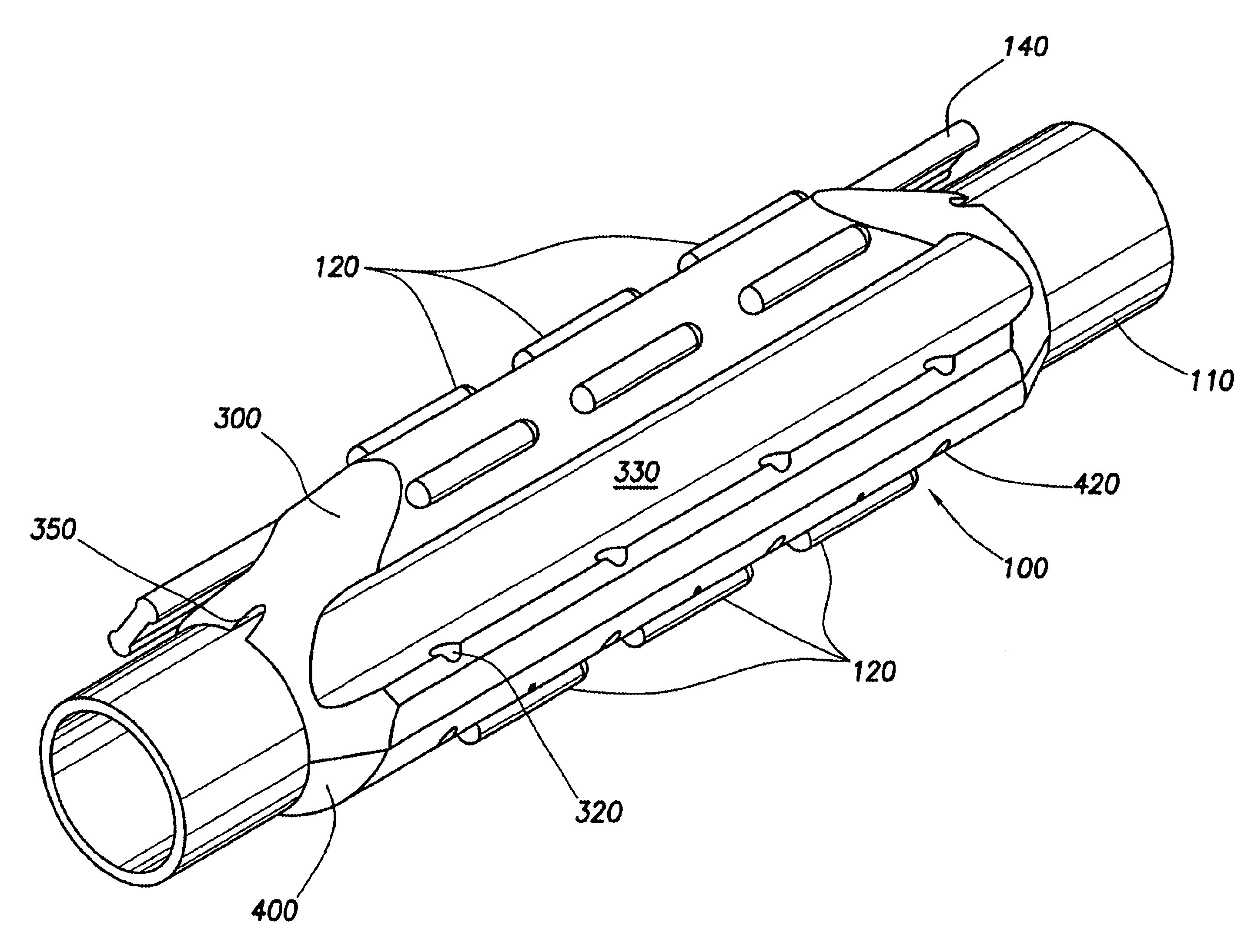
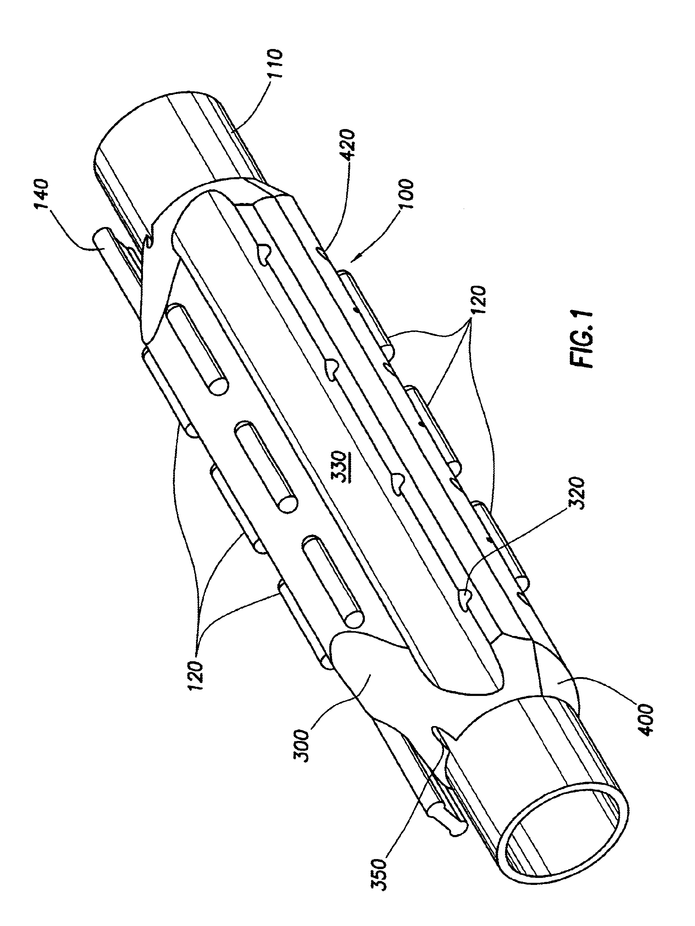
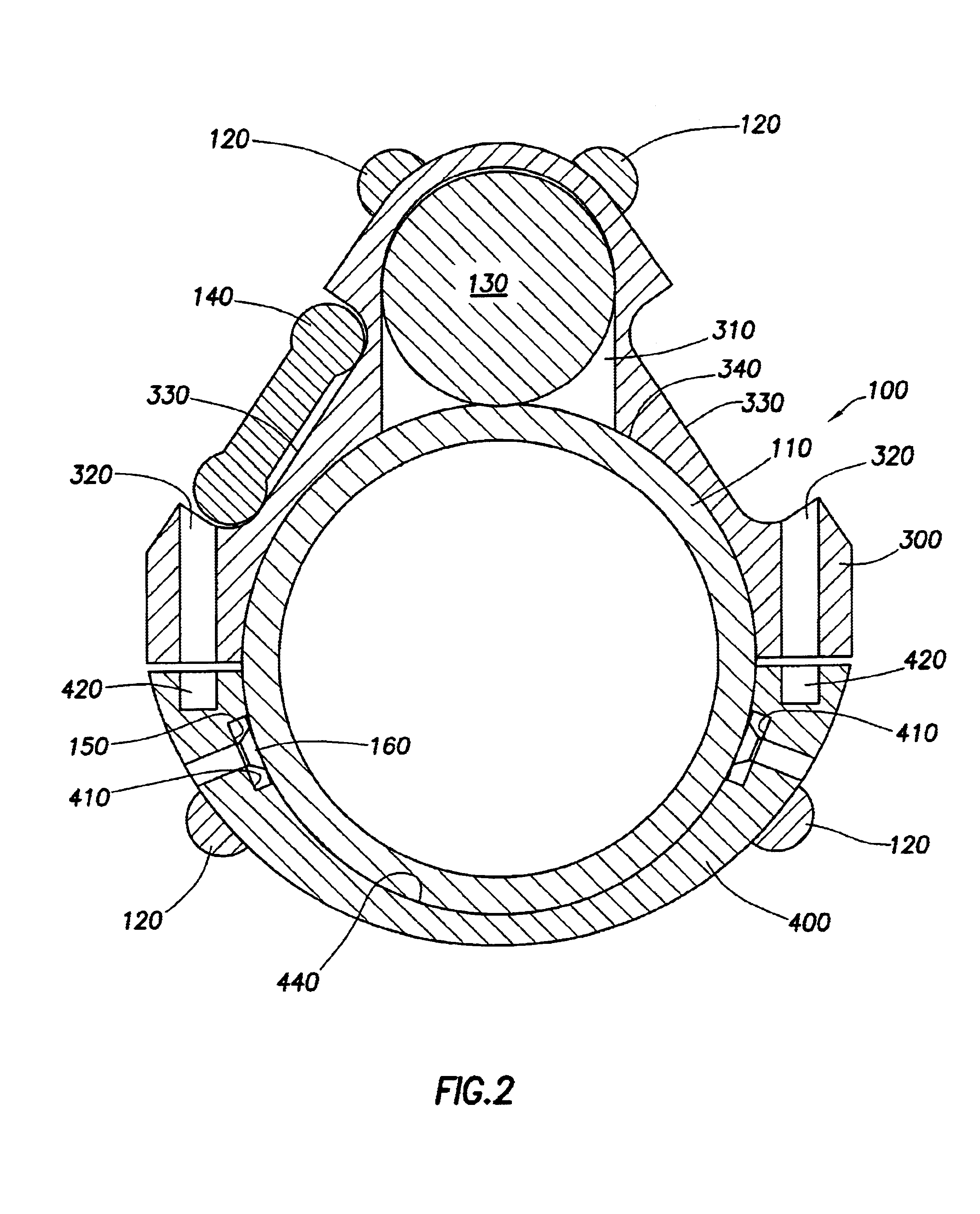
[0012]Accordingly, there is provided herein methods and apparatus for attaching a sensor to a tubing string for installation into a highly deviated wellbore. The preferred embodiments of the present invention are characterized by an apparatus for securely affixing a sensor to a tubing string, wherein the apparatus also provides a sufficient coupling to the casing of the wellbore. The embodiments of the present invention act to provide stable, reliable coupling between a sensor and the casing of a highly deviated wellbore. In this context a stable, reliable coupling is achieved when a sensor is maintained in a position to the wellbore where no relative motion occurs between the sensor and the wellbore during data acquisition.

[0013]In preferred embodiments, the invention includes at least the following embodiments. One embodiment of an apparatus for collecting data from a wellbore includes a sensor, a tubing string, and a connector that fixes the sensor to the tubing so that there is ...


PUM


Abstract

A method and apparatus, for deploying a sensor attached to tubing in a highly deviated or horizontal wellbore, that are characterized by a stationary attachment system that securely fixes a sensor to a tubing string such that the sensor is coupled to the casing regardless of the orientation of the tubing within the wellbore. One preferred embodiment includes a clamp assembly that encloses the sensor and clamps around the cubing string. The clamp assembly further includes a plurality of contact members that provide stable contact points between the well casing and the clamp assembly. The embodiments of the present invention act to maintain the sensor in a stable coupling with the casing without any actuation required for installation.

Description

CROSS-REFERENCE TO RELATED APPLICATIONS[0001]Not applicable.STATEMENT REGARDING FEDERALLY SPONSORED RESEARCH OR DEVELOPMENT[0002]Not applicable.BACKGROUND OF THE INVENTION[0003]The present invention relates generally to methods and apparatus for attaching a sensor to a tubing string for deployment within a wellbore. More specifically, the present invention relates to methods and apparatus for attaching a sensor to a tubing string for deployment within a highly deviated wellbore.[0004]During the production of hydrocarbons from an underground reservoir or formation, it is important to determine the development and behavior of the reservoir and to foresee changes which will affect the reservoir. Methods and apparatus for determining and measuring downhole parameters for forecasting the behavior of the reservoir are well known in the art.[0005]A standard method and apparatus includes placing one or more sensors downhole adjacent the reservoir and recording seismic signals generated from...

Claims


Application Information

Patent Timeline
Patent Type & Authority Patents(United States)
IPC IPC(8): E21B47/01E21B47/00
CPCE21B47/011E21B47/017E21B47/01
Inventor LINYAEV, EUGENE JOSEPHCHESNUTT, PATRICK DENNIS
Owner HALLIBURTON ENERGY SERVICES INC
Why Eureka
Try Eureka