Slide damper with spring assist

a damper and spring technology, applied in the field of sliding dampers, can solve the problems of increased damping, increased damping, and increased damping, and achieve the effect of reducing the amount of springs

Inactive Publication Date: 2005-06-28
ILLINOIS TOOL WORKS INC
View PDF8 Cites 45 Cited by
  • Summary
  • Abstract
  • Description
  • Claims
  • Application Information

AI Technical Summary

Benefits of technology

[0018]Engagement and disengagement of the damper (i.e., one-way damping) is provided by the movement of the damper assembly within the cover. In a present embodiment, the cover includes a recessed region in which the damper assembly is disposed. The recessed region includes teeth that engage the damper housing when the damper assembly is moved

Problems solved by technology

However, it has been found that an assist of sufficient strength to automatically and fully close a heavily loaded drawer or the like can result in abrupt movements and rapid closing.
At times, the “strength” of the assist results in a significant impact upon reaching the fully closed position.
In that the opposite (e.g., opening) motion may be done without mechanical assist, and in fact may itself be restrained by the expansion of an extension spring used to assist closing, further damping is not needed a

Method used


Image

  • Slide damper with spring assist
  • Slide damper with spring assist
  • Slide damper with spring assist

Examples


Embodiment Construction

[0028]While the present invention is susceptible of embodiment in various forms, there is shown in the drawings and will hereinafter be described a presently preferred embodiment with the understanding that the present disclosure is to be considered an exemplification of the invention and is not intended to limit the invention to the specific embodiment illustrated.

[0029]It should be further understood that the title of this section of this specification, namely, “Detailed Description Of The Invention”, relates to a requirement of the United States Patent Office, and does not imply, nor should be inferred to limit the subject matter disclosed herein.

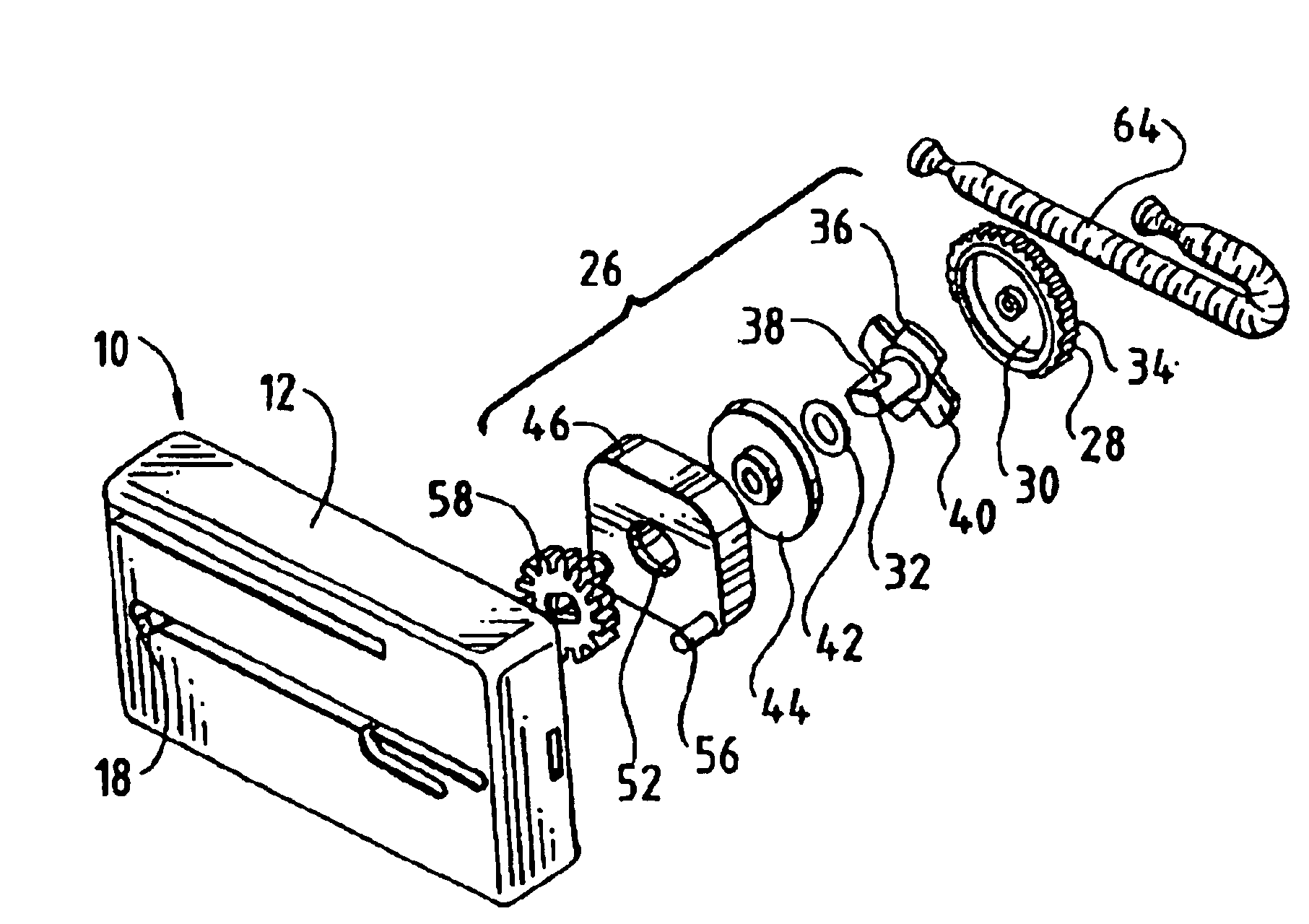
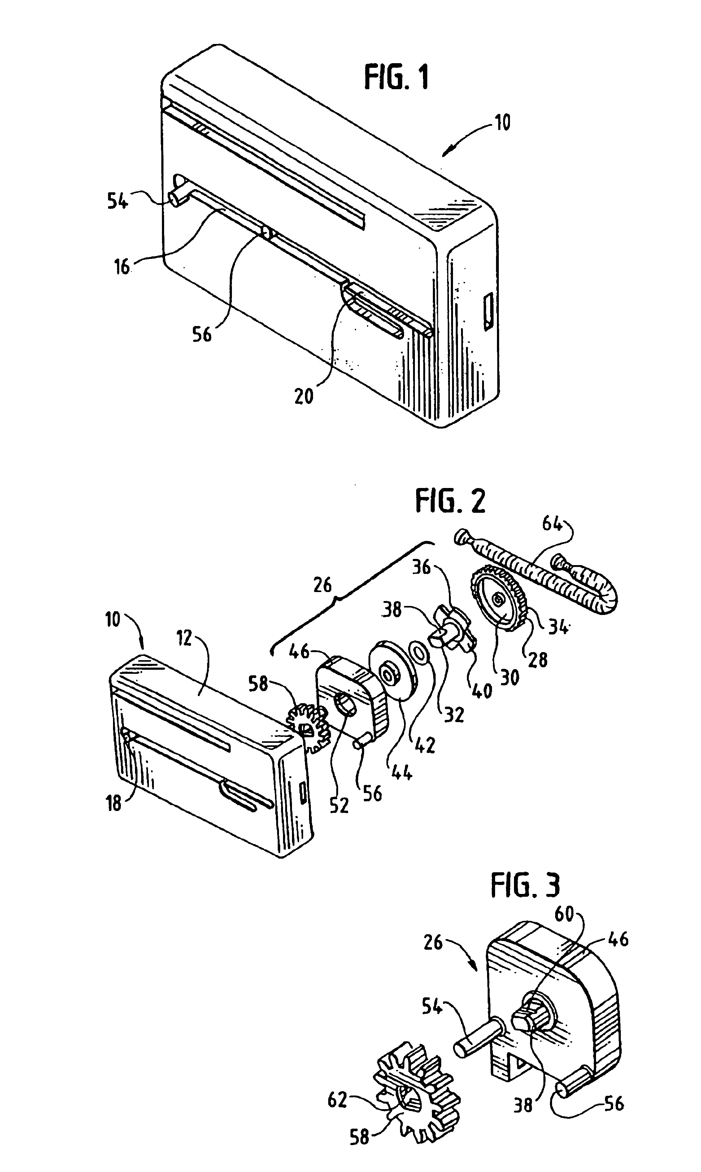
[0030]Referring now to the figures and in particular, to FIG. 1, there is shown a slide damper with spring assist 10 embodying the principles of the present invention. The present slide damper 10 uses a spring assist in a compact, integral unit for use in, for example a drawer, such that the damper is engaged and operational when the dra...


PUM


Abstract

A slide damper for use with an associated sliding object that is movable between a first position and a second position provides an assisted, dampened return. The slide damper includes a housing having a track, a gear on the housing and a cover configured for movement along the housing. The cover further includes a track engaging pin for engaging the housing track as the cover moves along the housing. A biasing element operably connects the cover and the housing to bias the cover to the second position. A damper assembly is disposed within the cover and includes a damper housing having a geared outer periphery, a damping material disposed in the damper housing and a rotor disposed at least in part within the damper housing for cooperating with the damping material. The rotor has a shaft and is rotatable relative to the damper housing. The rotor shaft extends through the cover and a damper gear operably connects the shaft and the housing gear. The damper assembly is selectively engaged in which the rotor rotates relative to the damper housing when the cover is moved toward the second position and movement of the damper gear along the housing gear is dampened, and disengaged in which the rotor is stationary relative to the damper housing when the cover is moved toward the first position and movement of the damper gear along the housing gear is unimpeded.

Description

BACKGROUND OF THE INVENTION[0001]The present invention relates to slide dampers. More particularly, the present invention relates to slide dampers for use with sliding objects, which slide dampers have a spring assist.[0002]Slides are used in a wide variety of applications. For example, slides may be used in conjunction with drawers, sliding racks, desk drawers, cabinets and the like to slide an object, such as a drawer, from another object, such as the cabinet in which the drawer is installed.[0003]Many such slide arrangements include an assist feature to assist in moving the object one way or the other. That is, a spring can be used to assist in closing a drawer from the open position. In a typical assisted arrangement, a spring is mounted along a rail of the slide assembly to “pull” the drawer closed, after closing action is begun.[0004]With conventional spring assists, the mechanism is self-closing, requiring only an initial start to unseat it from a secured, opened position. Su...

Claims


Application Information

Patent Timeline
IPC IPC(8): A47B88/04F16D57/00F16F9/12F16F13/00
CPCE05F3/14F16F13/00F16F9/12E05Y2201/21E05Y2201/266E05Y2201/254
Inventor DOORNBOS, DAVID A.BIVENS, STEVEN L.
Owner ILLINOIS TOOL WORKS INC
Why Eureka
Try Eureka