
Automotive lighting assembly cooling system

a cooling system and lighting assembly technology, applied in indirect heat exchangers, semiconductor devices of light sources, light and heating apparatus, etc., can solve the problems of easy breakage of filaments, high electrical power consumption, and large amount of hea

Inactive Publication Date: 2005-06-28
GUIDE
View PDF19 Cites 171 Cited by
  • Summary
  • Abstract
  • Description
  • Claims
  • Application Information

AI Technical Summary

Problems solved by technology

However, filament bulbs have many drawbacks, including high consumption of electrical power, the generation of great amounts of heat, and readily breakable filaments.
However, various other problems are associated with LEDs when used in automobile lighting systems.
Of course, as the power of the LED increases, the amount of heat generated also increases.
The increase in heat is a significant problem for LED systems.
While the expected lifetime of an LED at room temperature may be tens of thousands of hours, that same LED when exposed to high temperatures may only last several thousand hours.
Moreover, the amount of light emitted by an automotive lighting systems is a significant safety issue subject to various laws and regulations.
However, subjecting an LED to an increased temperature results in an immediate dimming of the LED at the time of exposure.
Moreover, as an LED is exposed to increased temperatures over a period of time, the maximum achievable output of the LED is diminished even during uses at lower temperatures.

Method used


Image

  • Automotive lighting assembly cooling system
  • Automotive lighting assembly cooling system
  • Automotive lighting assembly cooling system

Examples


Embodiment Construction

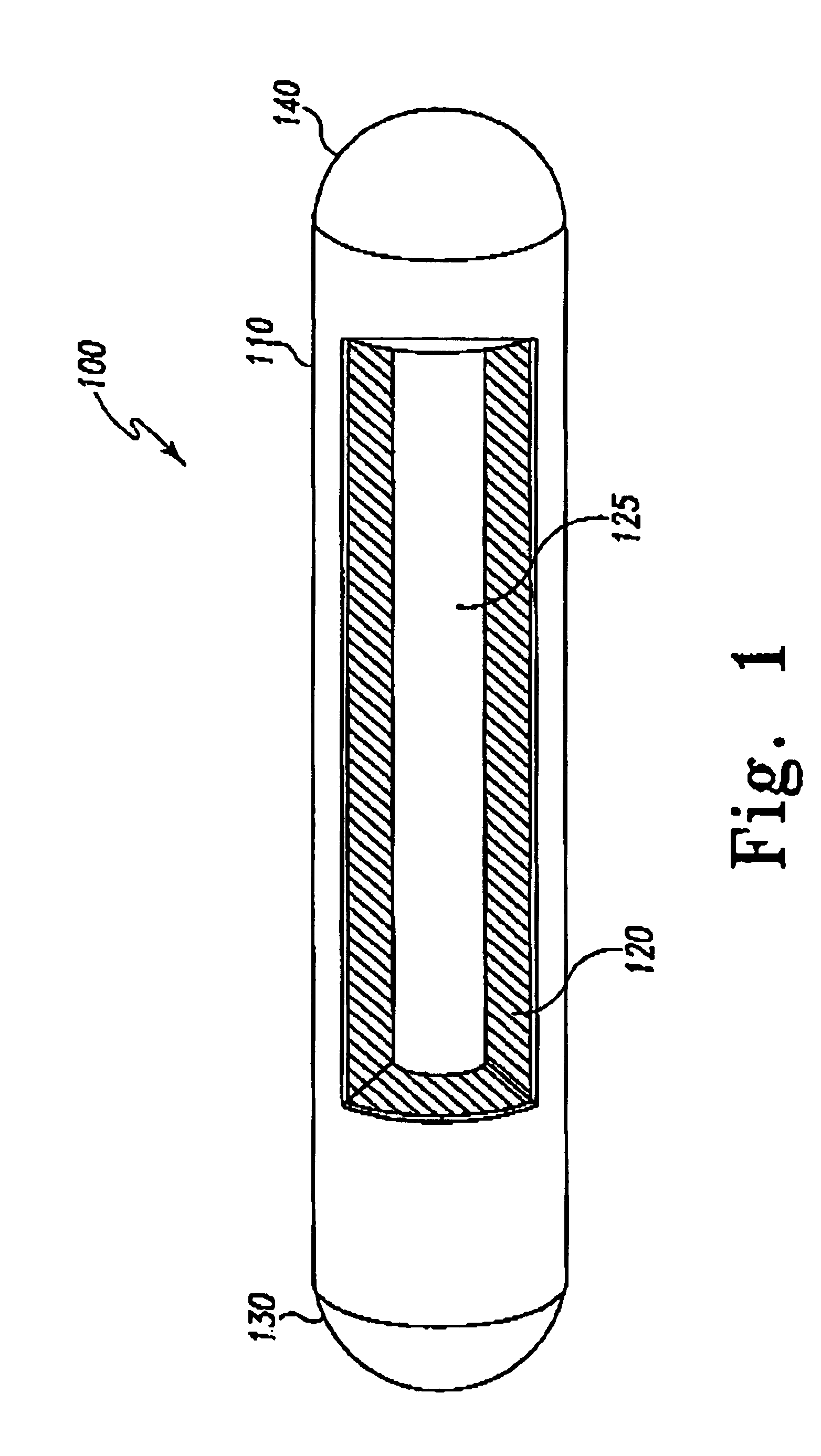
[0012]FIG. 1 is a partial cutaway view of a heat pipe. Heat pipe 100 comprises shell 110, wick 120, evaporation area 130 and condensation area 140. Wick 120 is initially saturated with a fluid such as deionized water. The basic operation of heat pipe 100 is as follows. Evaporation area 130 is placed so as to be thermally coupled to a heat generation site. Condensation area 140 is placed in an area which is at a lower temperature relative to the heat generating site. Thus, as heat is generated, the heat is transferred to heat pipe 100 at evaporation area 130. As heat is transferred to evaporation area 130, the fluid within wick 120 near to evaporation area 130 is heated. As the heated fluid reaches its vaporization temperature, the fluid is vaporized, thus absorbing more heat. The vaporized fluid expands into void 125 defined by shell 110, transferring heat by convection away from evaporation area 130.

[0013]The vaporized fluid expands within shell 110 to condensation area 140. Conden...


PUM


Abstract

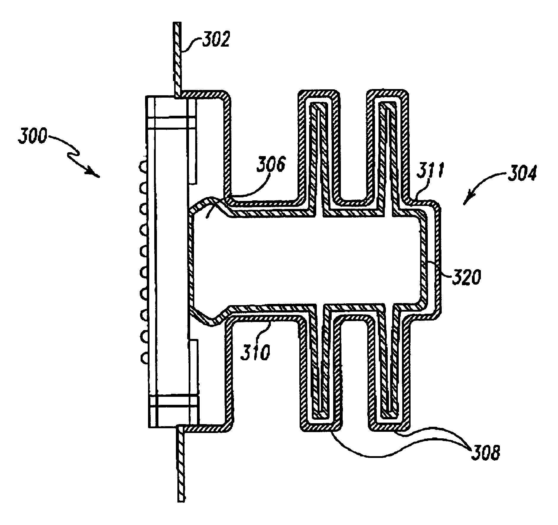
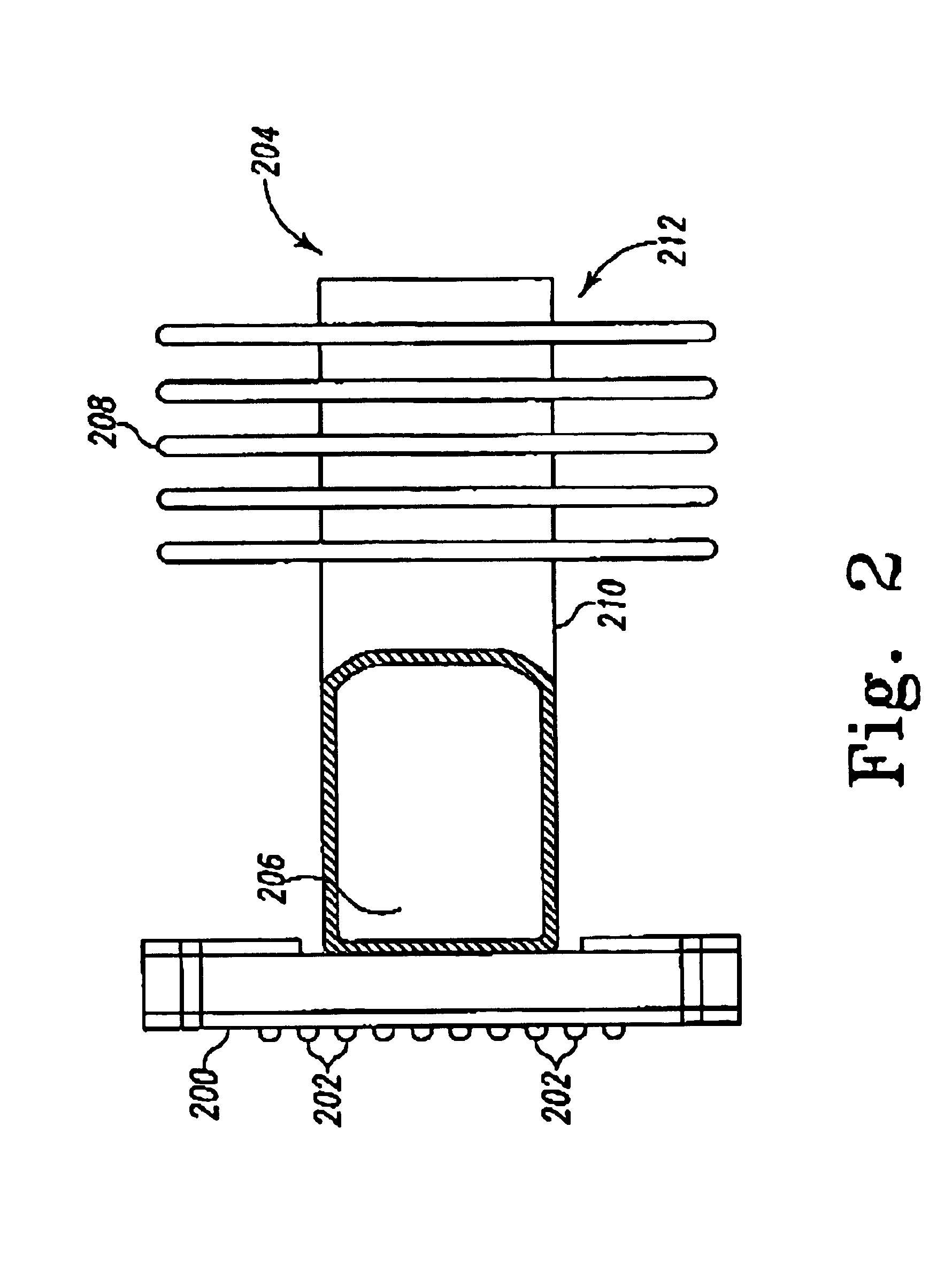
An automotive lighting assembly cooling system includes a heat pipe with an evaporation area proximate to a heat generating component, such as a Light Emitting Diode (LED), and a condensing area located remote from the evaporation area. Evaporation of fluid within the heat pipe transfers heat away from the heat generating component. The efficiency of the cooling system in one embodiment is increased by including fins associated with the condensing area and placing the fins in an area where air flow external to a moving vehicle assists in cooling the fins.

Description

BACKGROUND OF THE INVENTION[0001]Generally, conventional automotive lighting systems utilize filament bulbs as a lighting source. However, filament bulbs have many drawbacks, including high consumption of electrical power, the generation of great amounts of heat, and readily breakable filaments. Recently, due to these drawbacks, light emitting semiconductor devices (LESDs), such as light emitting diodes (“LEDs”), have been adapted for use in certain automobile lighting systems.[0002]LEDs solve many of the problems associated with filament bulbs, because they emit light using a lower voltage and current than used by a filament bulb and are less prone to breakage. However, various other problems are associated with LEDs when used in automobile lighting systems. For example, typical LEDs produce significantly less light than filament bulbs. Accordingly, a number of LEDs must be used within a particular light assembly to generate the requisite amount of light. As the number of LEDs is i...

Claims


Application Information

Patent Timeline
Patent Type & Authority Patents(United States)
IPC IPC(8): F21V29/00H01L33/00H01L33/64
CPCF21S48/328F21V29/004F21V29/006F28D15/0233F28D15/046F21V29/767H05K1/0209F21Y2101/02F28F1/26H01L33/648F28F2215/06H05K2201/10106F28F1/24F21V29/51F21V29/74F21Y2115/10F21S45/47F21S45/48
Inventor RICE, LAWRENCE M.
Owner GUIDE
Learn More