Shunt for squib having an improved securing mechanism

a technology of squib and shunt, which is applied in the direction of coupling device connection, pedestrian/occupant safety arrangement, vehicular safety arrangement, etc., can solve the problems of inadvertent disconnection of the shunt from the inflator, reduce the depth of the fitting of the swelled part into the fitting concave, and provide sufficient force, so as to reduce the force required to insert the shunt into the socket and enhance the workability of fitting th

Inactive Publication Date: 2005-06-28
JST MFG CO LTD
View PDF25 Cites 18 Cited by
  • Summary
  • Abstract
  • Description
  • Claims
  • Application Information

AI Technical Summary

Benefits of technology

[0006]The present invention was made in view of the above-mentioned points, and its object is to provide the outer face of the shunt body with a protrusion protruding obliquely, make the protrusion to be bent and deformed and shunt inward when the shunt is inserted into the socket, and make the protrusion restitute and protrude in the fitting concave when the shunt body is once fitted into the socket, so as to ensure the inflator yields a force sufficient to hold the shunt, prevent the shunt from coming off the inflator, reduce the force required to insert the shunt into the socket, and enhance the workability of assembling the shunt into the socket.
[0009]To fit the shunt into the socket, when the shunt body is inserted into the socket, the top end of the protrusion will be pushed by the inner circumferential face of the socket toward the connection hole of the shunt body, and the protrusion will be bent and deformed to shunt toward the connection hole. In this case, as the protrusion is deformed by bending, greater displacement of the top ends thereof can be obtained by a small force when compared with a case wherein the swelled part and the shunt body are to be deformed by compression. Accordingly, when compared with a case wherein the swelled part is provided on the outer circumferential face of the shunt body, the frictional force working on the protrusion and the inner circumferential face of the socket is reduced. As a result, the force required to insert the shunt into the socket will be reduced, and the workability of fitting the shunt into the socket will be enhanced.
[0010]When the shunt body is fitted into the socket, the protrusion will restitute and protrude, with a sufficient length, in the fitting concave. Moreover, as the frictional forces working on the protrusion and the inner circumferential face of the socket are reduced, gnawing of the protrusion will be reduced. Accordingly, the depth of fitting between the protrusion and the fitting concave is sufficiently large, and in turn, the force of holding the shunt by the inflator is improved, and disconnection of the shunt from the inflator can be prevented reliably.
[0011]When the protrusion protrudes into the fitting concave, the top end of the protrusion will undergo a large deformation as the protrusion restitutes itself from a deformed state by bending. Hence a conspicuous response will be experienced with a clear sense of clicking. As a result, it is easier to verify that the protrusion has been fitted into the fitting concave; it will be hard to leave the fitting work half done or incomplete. Accordingly, the force of holding the shunt by the inflator is enhanced, and disconnection of the shunt from the inflator can be prevented reliably.
[0012]In the shunt for squib according to the present invention, the outer face of the shunt body is provided with a protrusion protruding obliquely, and when the shunt is inserted into the socket, the protrusion will be deformed by bending to shunt inward, and when the shunt body is fitted into the socket, the protrusion will restitute itself to protrude in the fitting concave. As a result, the depth of fitting between the protrusion and the fitting concave is sufficiently large, and fitting of the protrusion into the fitting concave can be verified easily with a sense of clicking to prevent incomplete fitting. Accordingly, the force of the inflator to hold the shunt is enhanced, and disconnection of the shunt from the inflator can be prevented reliably. Moreover, the force required to insert the shunt into the inflator is reduced, and the workability of fitting the shunt into the inflator is enhanced.

Problems solved by technology

Moreover, the swelled part is gnawed (i.e. fretted or chafed) by friction against the inner circumferential face of the socket while the shunt is moved toward the bottom of the socket, and this reduces the depth of fitting of the swelled part into the fitting concave.
As a result, the inflator cannot provide a sufficient force to hold the shunt, causing troubles such as inadvertent disconnection of the shunt from the inflator during transportation.
Moreover, if the depth of fitting of the swelled part in the fitting concave is small, the feel or response at the time of fitting is small or the so-called sense of clicking is wanted, and it is hard to confirm the successful fitting.
This may confuse one to think that the parts are fitted together although they are only in a half-fitted or incompletely-fitted state.
Furthermore, when the shunt is to be fitted into the socket, the required insertion force will be large due to the friction between the swelled part and the inner circumferential face of the socket, impairing the workability of assembly.

Method used


Image

  • Shunt for squib having an improved securing mechanism
  • Shunt for squib having an improved securing mechanism
  • Shunt for squib having an improved securing mechanism

Examples


Embodiment Construction

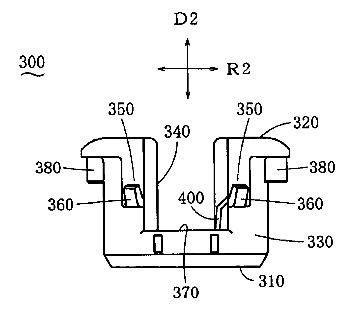
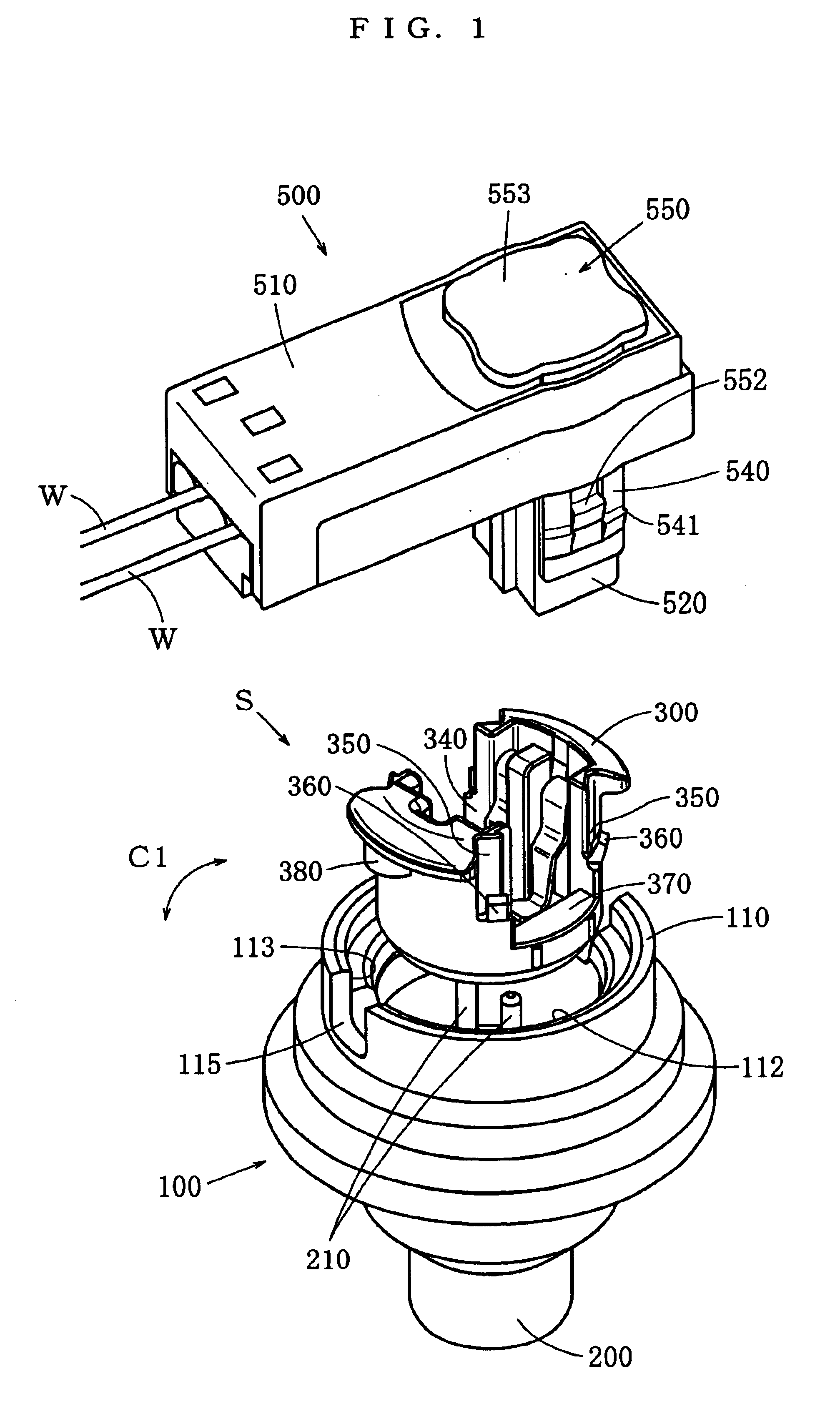
[0027]In the following, some embodiments of a shunt S of a squib according to the present invention will be described. FIG. 1 shows a shunt S of the first embodiment and members around it. 100 denotes a housing of an inflator. A squib 200, which receives electric energy to generate heat, is fixed inside the housing 100, and an igniter and a gas generator are arranged around the squib 200. An airbag in a deflated state is stored in the back of the inflator. When the squib 200 receives electric energy to generate heat, the igniter will be ignited, and it in turn will make the gas generator generate a gas, and the gas will deploy the airbag.

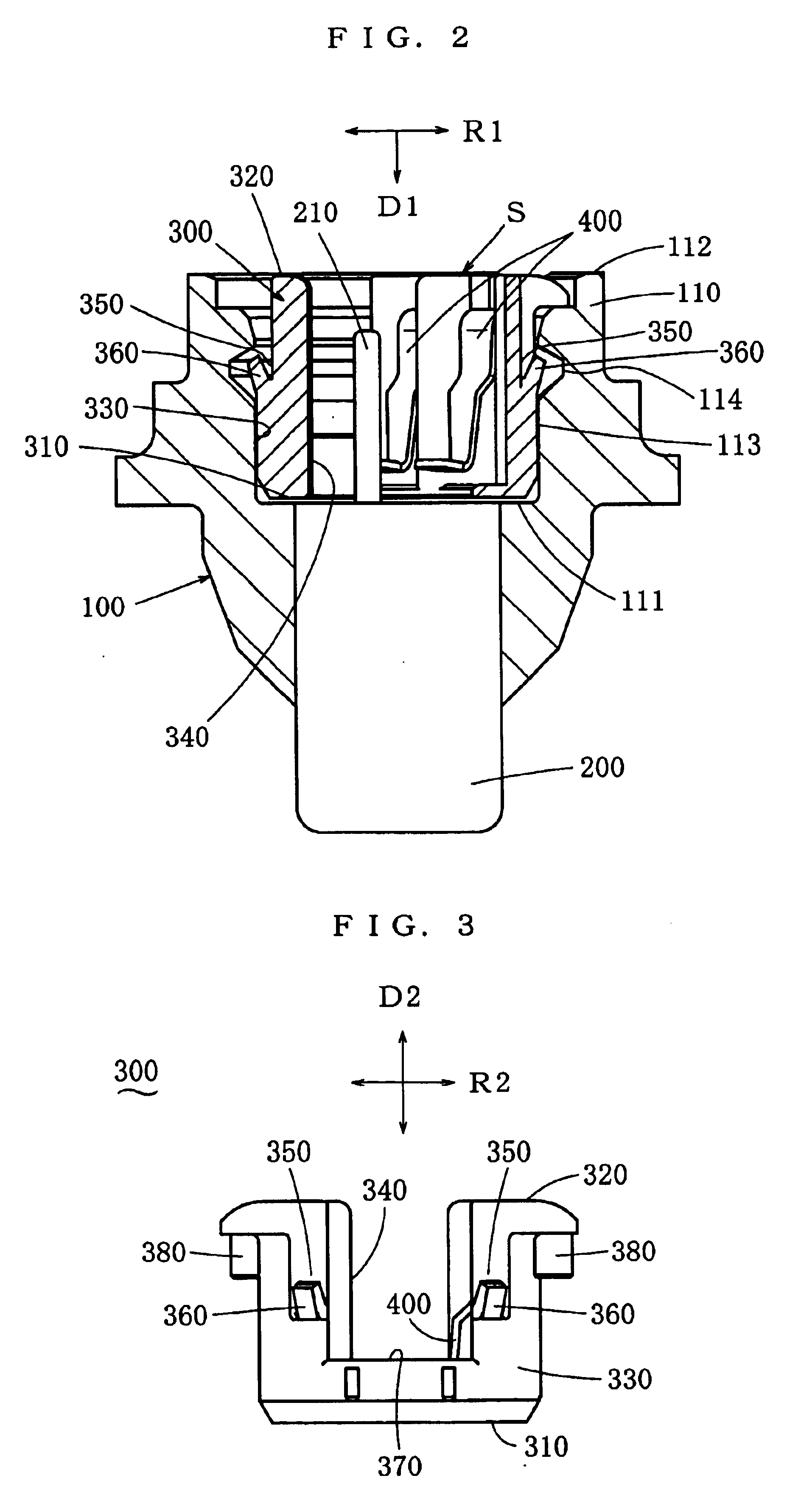
[0028]As shown in FIG. 1 and FIG. 2, the housing 100 of the inflator is provided with a socket 110. The socket 110 opens at the surface of the housing 100, and the socket 110 is cylindrically concaved into the housing 100 from this opening 112. As for the socket 110, a direction being parallel to the central axis of the cylinder and heading toward t...


PUM


Abstract

The objective is to ensure the inflator yields a force sufficient to hold the shunt, prevent the shunt from coming off the inflator, reduce the force required to insert the shunt into the socket, and enhance the workability of assembling the shunt into the socket. The shunt body is provided with a short-circuit piece which short-circuits the pair of pins of the squib, and the shunt body is provided with a protrusion being formed of a flexible material, the root end of the protrusion is provided on the outer face of the shunt body, the protrusion extends from the root end thereof in a direction tilting toward the outside from the shunt body at an angle within 90 degrees to a direction being parallel to the central axis of the shunt body and heading toward the top thereof, and it is arranged that when the top end of the protrusion is pushed toward the connection hole of the shunt body, the protrusion will undergo deformation by bending, and when the shunt body fits into the socket, the protrusion will restitute to protrude in the fitting concave.

Description

BACKGROUND OF THE INVENTION[0001]1. Field of the Invention[0002]An inflator for feeding a gas into an airbag to deploy it is provided with a squib (heat generator). To supply this squib with electric energy, a female connector is connected to a pair of pins of the squib. The present invention relates to a shunt, which short-circuits the pair of pins of the squib till the female connector is connected to the pair of pins.[0003]2. Related Art[0004]A shunt is known as a shunt of this kind, the shunt fits into a socket opening in the surface of a housing of an inflator and concaving from the opening in a cylindrical form into the housing and short-circuits a pair of pins of a squib rising from the bottom of the socket. The shunt comprises a shunt body formed into a cylinder to fit into the socket, and a short-circuit piece provided to the shunt body. When the shunt body is fitted into the socket, the short-circuit piece will short-circuit the pair of pins of the squib to prevent any mal...

Claims


Application Information

Patent Timeline
Patent Type & Authority Patents(United States)
IPC IPC(8): B60R21/26F42B3/26F42B3/182F42B3/00H01R13/703H01R13/627H01R13/70B60R21/264H01R13/46H01R13/639H01R13/64
CPCB60R21/26H01R13/7032F42B3/26H01R13/6273F42B3/182B60R2021/26029H01R13/64H01R13/46
Inventor OSADA, TSUYOSHI
Owner JST MFG CO LTD
Why Eureka
Try Eureka