Method of manufacturing eyewear

a manufacturing method and eyewear technology, applied in the field of eyewear, can solve the problems of not forming an ad hoc network consisting of more than two devices, conventional audio devices that do not function well in a noisy radio environment, and are limited to handling one to one communication, etc., and achieves low power consumption, small size, and high power consumption.

Inactive Publication Date: 2005-06-28
III HLDG 4
View PDF16 Cites 47 Cited by
  • Summary
  • Abstract
  • Description
  • Claims
  • Application Information

AI Technical Summary

Benefits of technology

[0008]Conventional apparatuses are limited to handling a one to one communication, and can not form an ad hoc network consisting of more than two devices. Conventional audio devices do not function well in a noisy, radio environment and are bulky and have high power consumption. Therefore, it is desirable to provide a wireless communication device that is capable of forming an ad hoc network with a plurality of devices. It is also desirable to provide an apparatus that is low-cost, small in size, and has a low power consumption. It is also desirable to have an apparatus that can function in very noisy radio environments and is audible under severe conditions.

Problems solved by technology

Conventional apparatuses are limited to handling a one to one communication, and can not form an ad hoc network consisting of more than two devices.
Conventional audio devices do not function well in a noisy, radio environment and are bulky and have high power consumption.
The transceivers limit their output power to exactly that actually needed.

Method used


Image

  • Method of manufacturing eyewear
  • Method of manufacturing eyewear
  • Method of manufacturing eyewear

Examples


Embodiment Construction

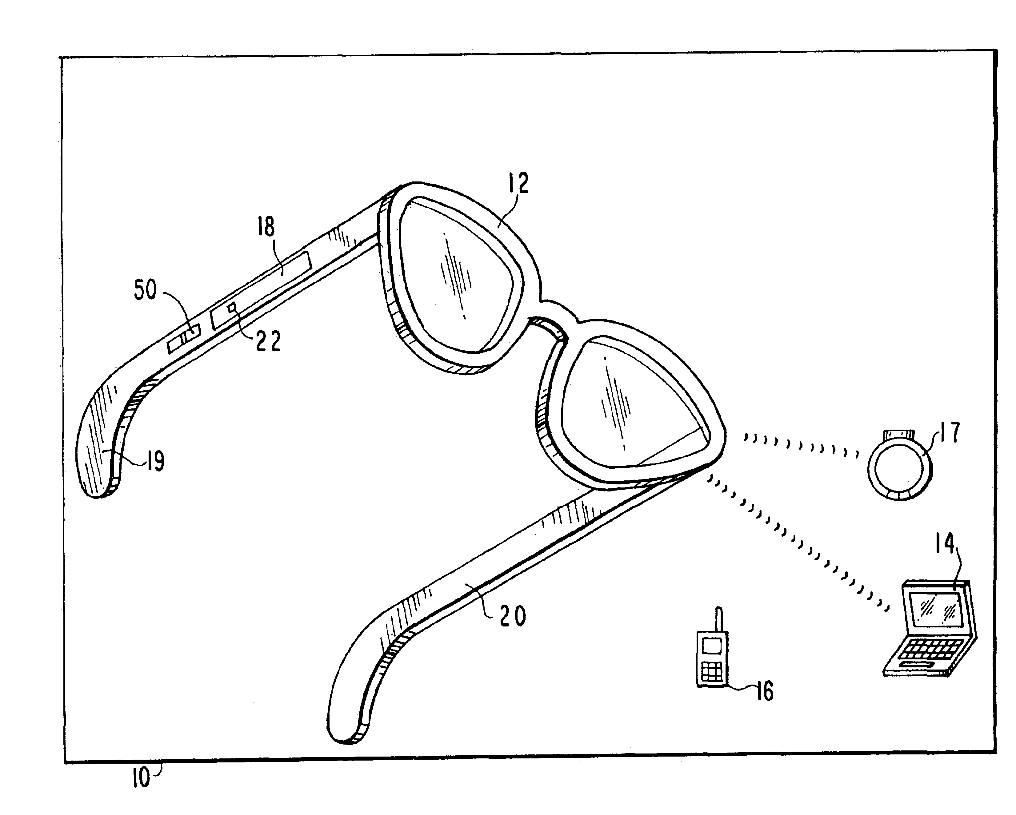
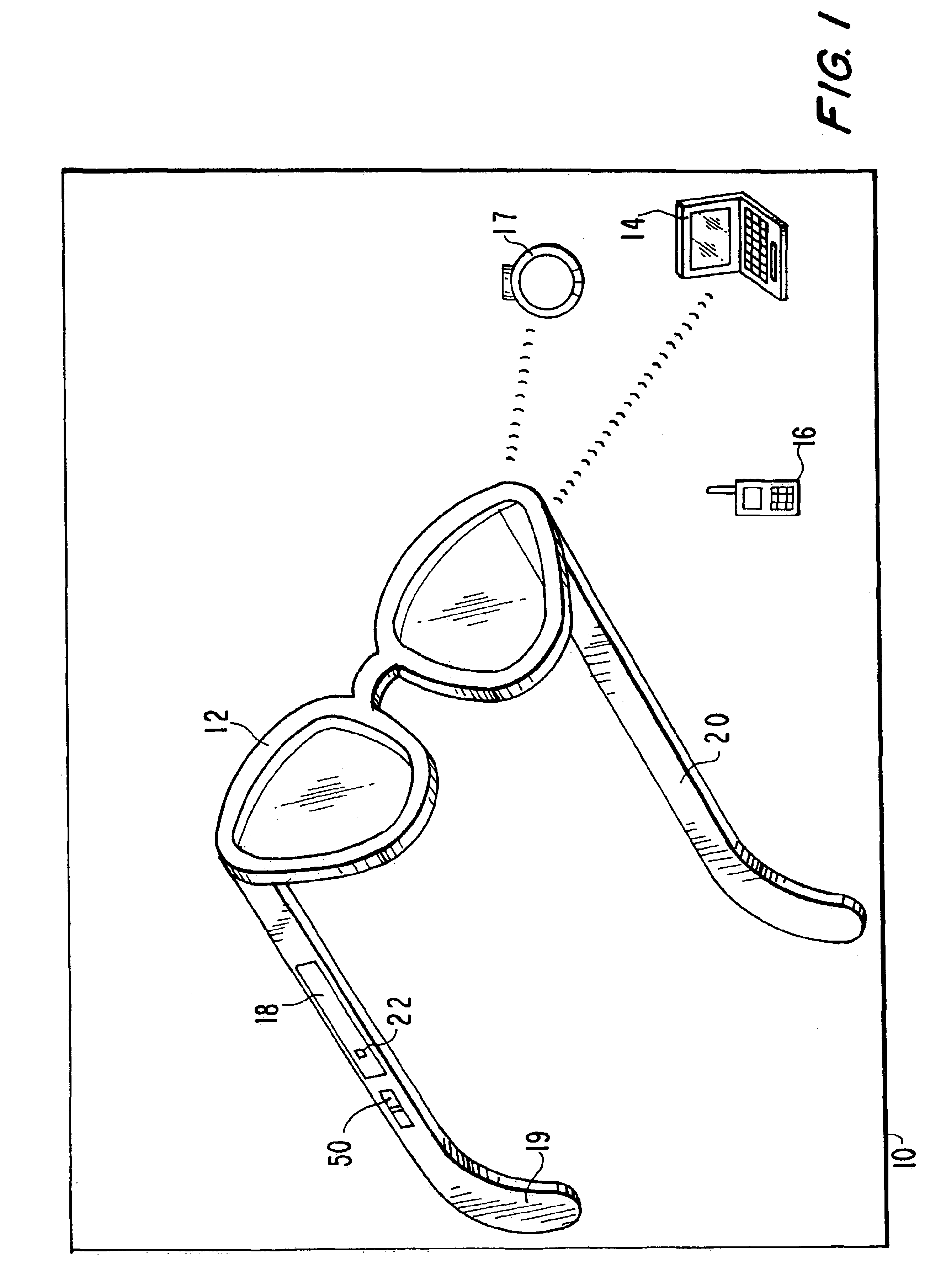
[0033]A general concept of the preferred embodiment of the present invention is shown in FIG. 1. In accordance with this embodiment, a wireless network 10 is formed by connecting eyewear 12 with computer 14, bracelet 17 and telephone 16. Eyewear 12 has a transceiver 18 mounted on one of the temples of the eyewear 12 (shown on the temple 19). Computer 14, bracelet 17 and telephone 16, also have similar transceivers, (not shown), mounted on them. When a user of the eyewear 12 comes within a predetermined distance from the above devices, the transceivers of the eyewear and these devices start to communicate to each other thereby creating the ad hoc small-range wireless network 10.

[0034]Transceiver 18 is a tiny, inexpensive, short range transceiver that operates on globally available, unlicensed radio band, 2.45 gigahertz(GHz). Transceiver 18 conforms to the BLUETOOTH™ standard. BLUETOOTH™ is an open specification technology, whose specifications can be obtained from BLUETOOTH™ SIG, Inc...


PUM

PropertyMeasurementUnit
distanceaaaaaaaaaa
radio frequency or infrared frequencyaaaaaaaaaa
power consumptionaaaaaaaaaa

Abstract

A wireless ad hoc pico network is formed by eyewear and other devices such as a computer, a bracelet and a telephone having similar transceivers mounted on them. The eyewear includes a frame and connected to the frame are two temples. Temples are connected to frame via hinges. Temples have a male portion of a connector incorporated in them. Female portion of the connector is made integral with the hinges. When the male portion is inserted in the female portion the temple is attached to the frame. The temples can be removed by pulling the connector apart, and a temple with different apparatus within it can be inserted in place of the removed temples. The temple may have co-molded within its body, an apparatus such as an audio device, a camera, a speaker, and a microphone, and a display device such as liquid crystal or an alarm.

Description

CROSS REFERENCE TO RELATED APPLICATIONS[0001]This application is a divisional application of U.S. patent application Ser. No. 09 / 845,425 filed Apr. 30, 2001 now U.S. Pat. No. 6,769,767 claims all rights of priority thereto.BACKGROUND OF THE INVENTION[0002]1. Field of the Invention[0003]The present invention relates to a wireless communication eyewear device having interchangeable temples. More particularly, the invention relates to eyewear having a transceiver enabled with small-range wireless communication technology.[0004]2. Description of the Related Art[0005]Many conventional wearable personal apparatus including eyewear, having electrical input-output devices are available to the consumers. Several of these apparatus provide wireless communications using radio frequency or infrared frequency. For example, U.S. Pat. No. 6,091,832 discloses a wearable personal apparatus that includes an audio transducer, which may function as an audio input or output device. The audio input or ou...

Claims


Application Information

Patent Timeline
Patent Type & Authority Patents(United States)
IPC IPC(8): G02C11/00G02C11/06G02C11/02B07C5/34G01N15/14G01N30/02G06F1/16G21K1/00H04B7/00H04L12/28H04M1/00H04W4/80
CPCG02C11/10G01N30/02Y10T16/526B01D2015/3895H04W4/80B29D12/02H04W56/0015G02C5/146G02C5/22G06F1/163H04W52/248H04W84/18
Inventor SWAB, GREGORYMALACKOWSKI, JAMES E.GREAVES, MIKALMILESI, ROLFLIGTENBERG, CHRISTINEMEIER, THOMAS
Owner III HLDG 4
Why Eureka
Try Eureka