Oled display having color filters for improving contrast

Inactive Publication Date: 2005-06-28
GLOBAL OLED TECH
View PDF18 Cites 61 Cited by
  • Summary
  • Abstract
  • Description
  • Claims
  • Application Information

AI Technical Summary

Benefits of technology

[0008]The present invention has the advantage that it increases the contrast of an O

Problems solved by technology

If the portion of the light emitted toward the back is absorbed, it is absorbed and lost.
If the contrast is very low, it is difficult for a viewer to see the display light rather than the ambient light.
Unfortunately,

Method used


Image

  • Oled display having color filters for improving contrast
  • Oled display having color filters for improving contrast
  • Oled display having color filters for improving contrast

Examples


Embodiment Construction

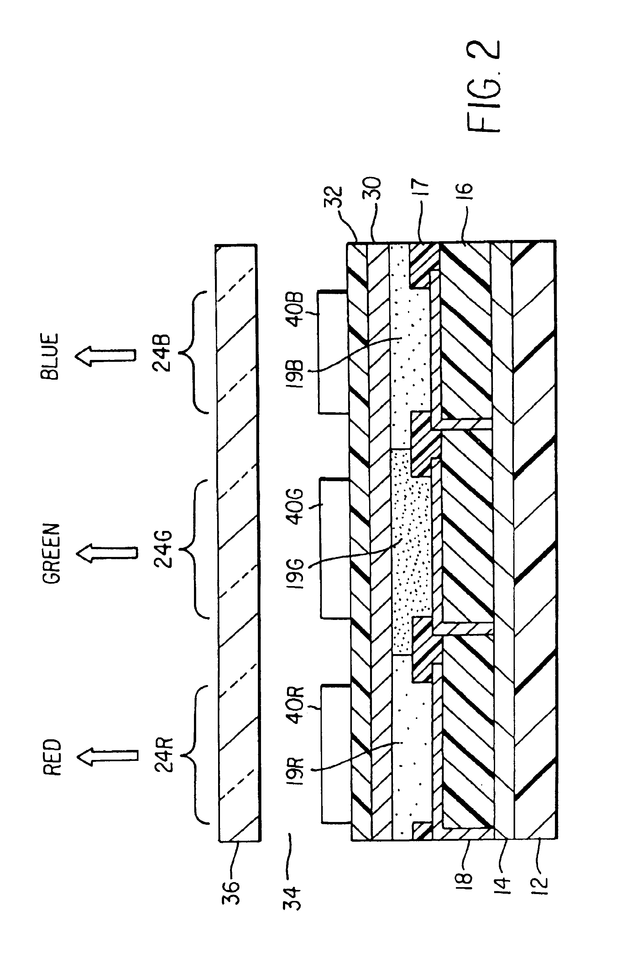
[0015]The present invention is useful for both top-emitting OLED display devices (those that emit light through a cover placed above a substrate on which the OLED is constructed) and bottom-emitting OLED display devices (those that emit light through the substrate on which the OLED is constructed).

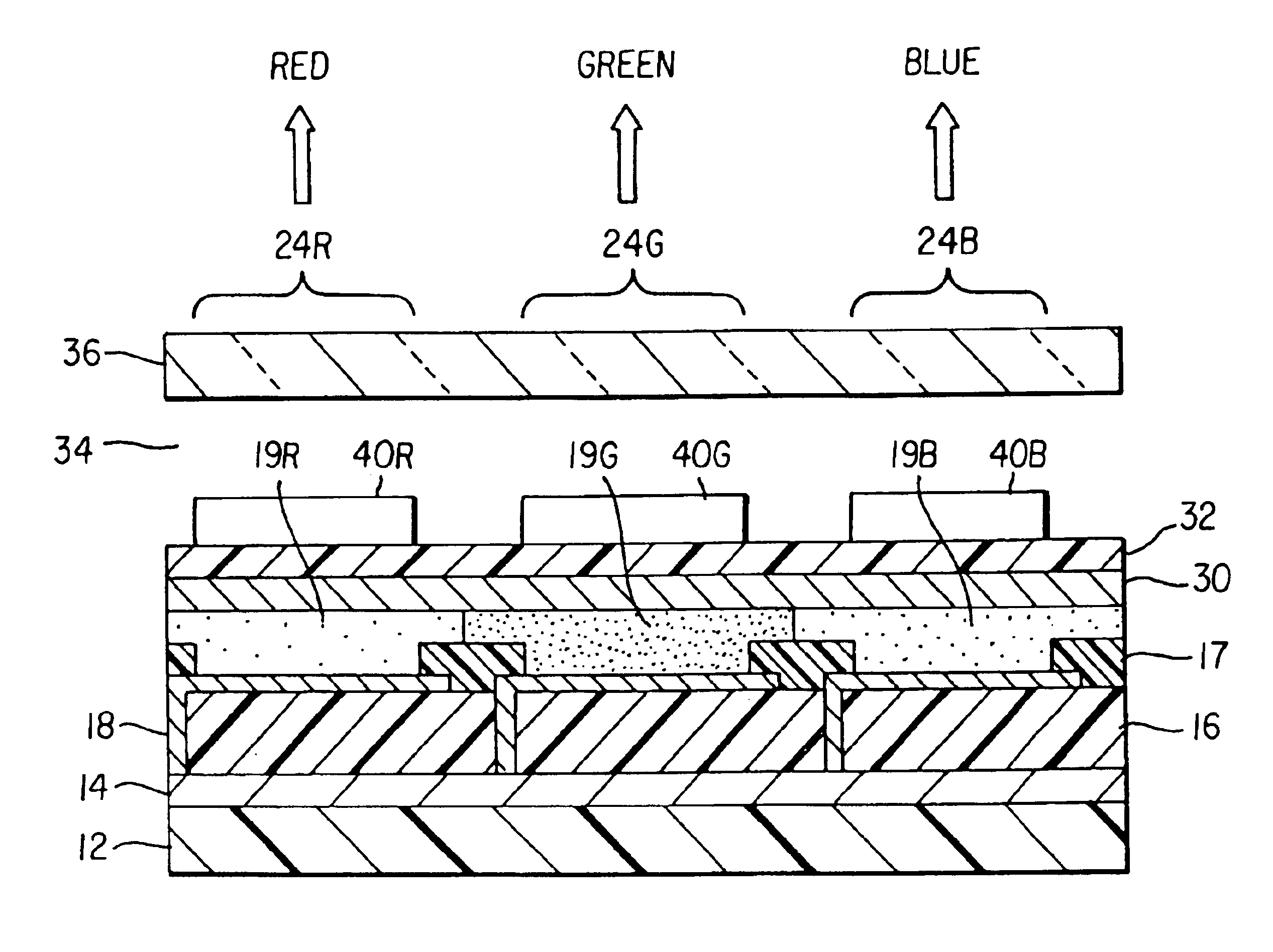
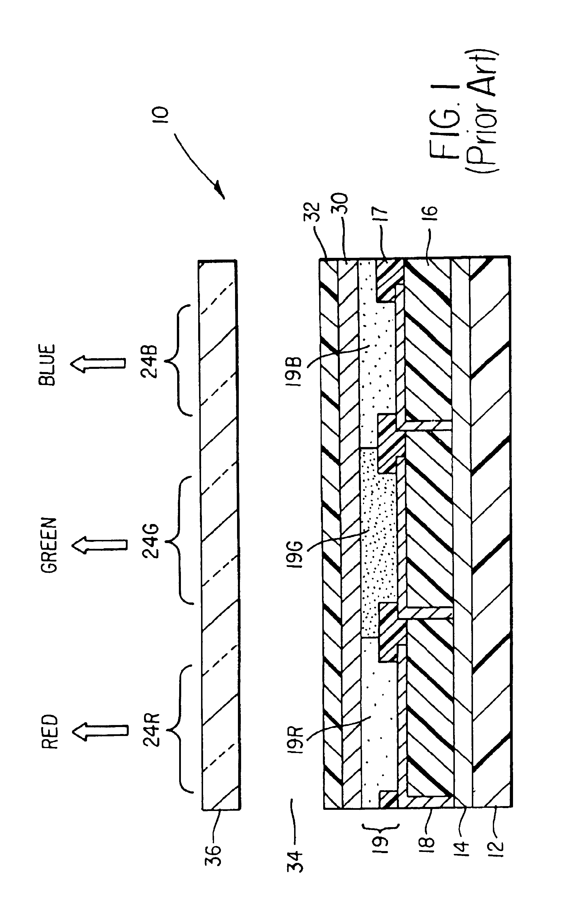
[0016]Referring to FIG. 1, a prior art top-emitting OLED display device 10 is shown with a substrate 12, and a thin-film transistor (TFT) active matrix layer 14 comprising an array of TFTs that provides power to OLED elements. A patterned first insulating layer 16 is provided over the TFT active matrix layer, and an array of first electrodes 18 are provided over insulating layer 16 and in electrical contact with the TFT active matrix layer. A patterned second insulating layer 17 is provided over the array of first electrodes 18 such that at least a portion of each of the first electrodes 18 is exposed.

[0017]Over the first electrodes and insulating layers are provided red, green, and blue-e...


PUM


Abstract

An OLED display device for displaying a color image, the display device being viewed from a front side includes a plurality of OLED elements including first color elements that emit a first color of light and second color elements that emit a second color of light different from the first color; a reflector located behind the OLED elements; and a corresponding plurality of filter elements aligned with the OLED elements, including first and second color filters for passing the first or second color of light emitted by the corresponding OLED element, and blocking other colors of light.

Description

FIELD OF THE INVENTION[0001]The present invention relates to organic light emitting diode (OLED) displays, and more particularly, to OLED displays having improved contrast and color gamut.BACKGROUND OF THE INVENTION[0002]Organic light-emitting diode (OLED) display devices utilize a current passed through thin-film layers of organic materials to generate light. Electrodes located on either side of the organic layers provide current to the organic layers. The color of the light depends on the specific organic material and the light is Lambertian and emitted in every direction. A portion of the light is emitted directly toward the front of the display device: through a substrate (for a bottom emitter device) or an encapsulating cover (for a top emitter device). A similar portion of the light is emitted toward the back of the display device and may be either absorbed or reflected by a layer behind the organic layers. If the portion of light emitted toward the back is reflected, it can p...

Claims


Application Information

Patent Timeline
IPC IPC(8): H01L27/32H01L51/52H01L27/28H01L51/50H01L51/30H01L51/05H01L51/00H05B33/12H05B33/22
CPCH01L27/3211H01L27/322H01L51/5281H01L27/3244H01L51/005H01L51/0052H01L2251/5315H01L51/0077H01L51/0081H01L51/5271H01L51/5284H01L51/0059H10K59/35H10K59/38H10K59/12H10K85/60H10K85/615H10K85/631H10K85/30H10K85/324H10K50/856H10K50/86H10K50/865H10K2102/3026H05B33/22
Inventor COK, RONALD S.
Owner GLOBAL OLED TECH
Why Eureka
Try Eureka