Pulsed eddy current sensor probes and inspection methods

a technology of eddy current sensor and probe, which is applied in the direction of magnetic property measurement, material magnetic variables, instruments, etc., can solve the problems of subsurface flaws, component failures, and time-consuming to achieve full coverage with a single eddy current prob

Inactive Publication Date: 2005-06-28
GENERAL ELECTRIC CO
View PDF23 Cites 83 Cited by
  • Summary
  • Abstract
  • Description
  • Claims
  • Application Information

AI Technical Summary

Problems solved by technology

Corrosion and fatigue are potential sources of damage to the airframe, which may cause subsurface flaws.
The presence of both surface cracks and subsurface flaws in metallic structures, such as aircraft skin structures, have the potential to lead to component failure.
Naturall

Method used


Image

  • Pulsed eddy current sensor probes and inspection methods
  • Pulsed eddy current sensor probes and inspection methods
  • Pulsed eddy current sensor probes and inspection methods

Examples


Embodiment Construction

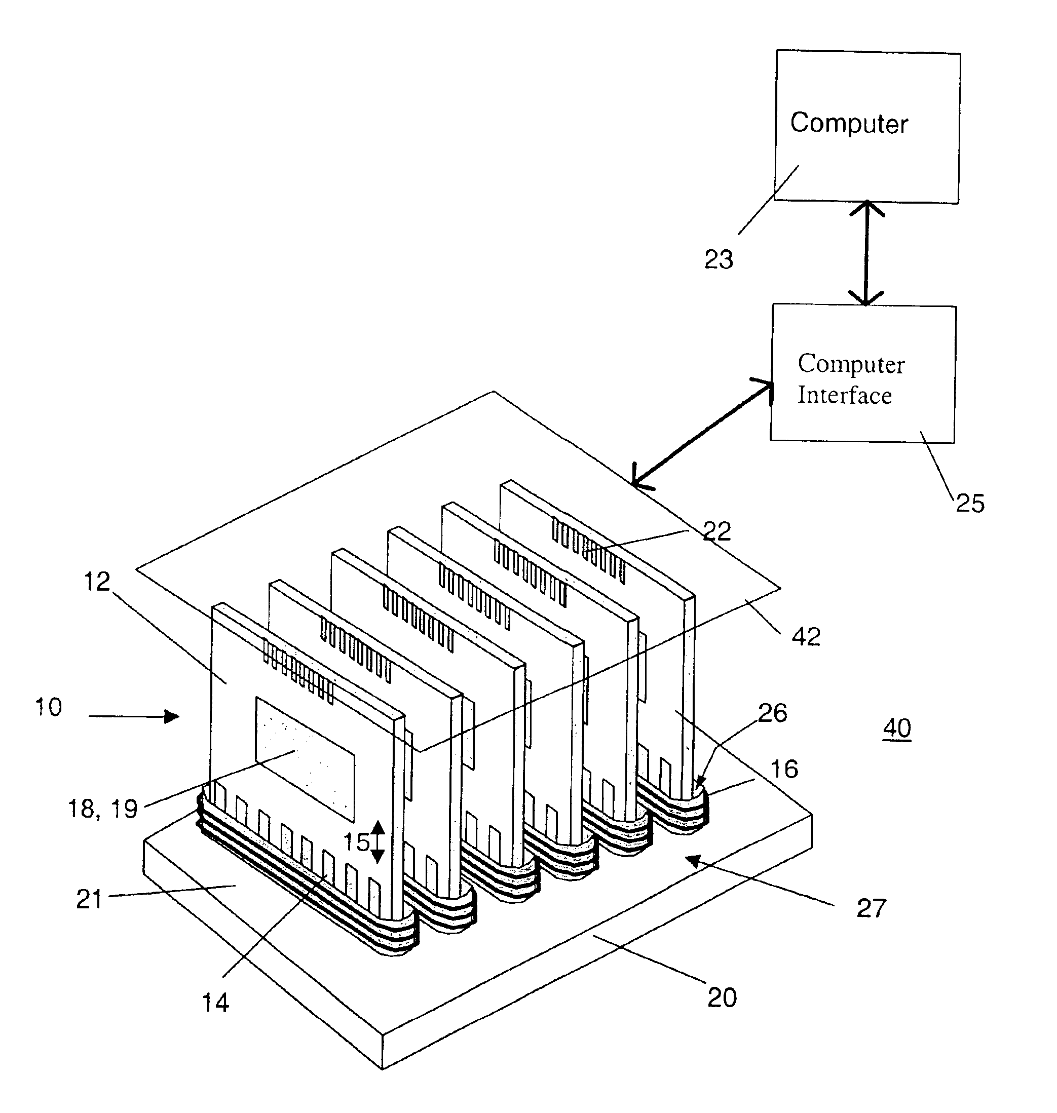
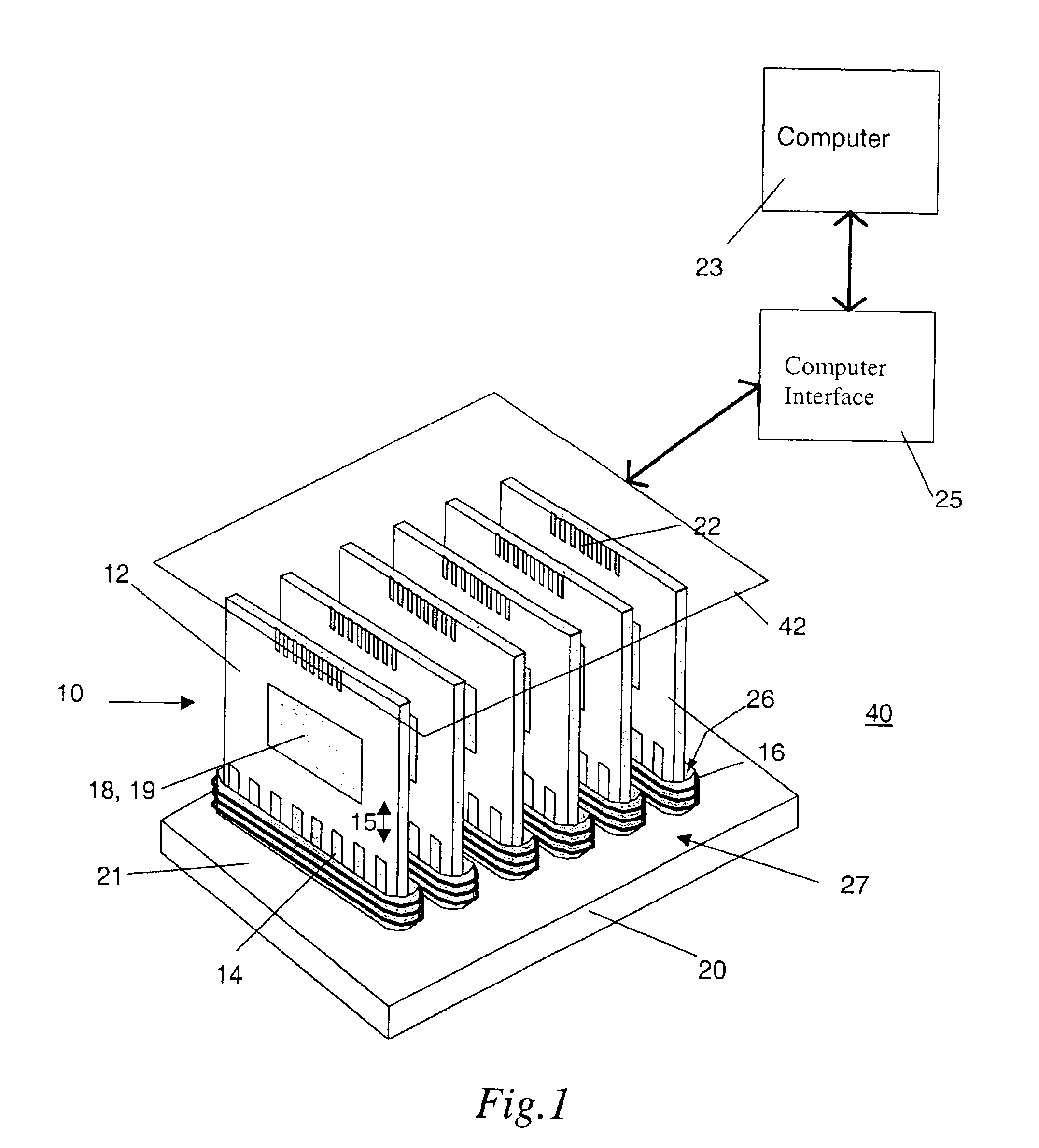
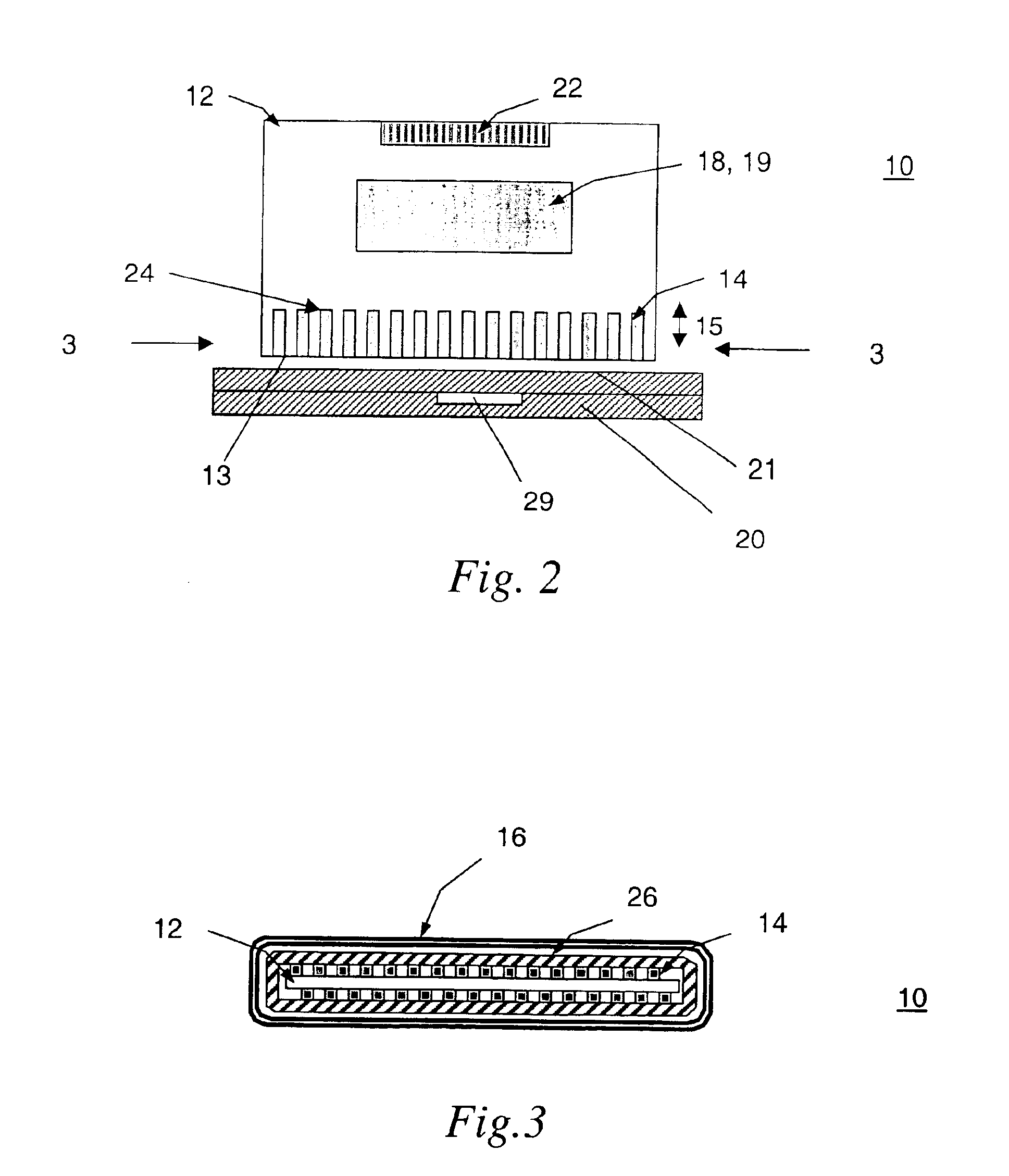
[0024]A pulsed eddy current (PEC) sensor probe 10 embodiment of the invention is described with reference to FIGS. 1-4. As shown, for example in FIGS. 1 and 2, the PEC sensor probe 10 includes a sensor array board 12. An exemplary sensor array board 12 is a printed circuit board (PCB) 12. The PEC sensor probe 10 further includes a number of sensors 14 arranged on the sensor array board 10. The sensors 14 are operable to sense and generate output signals from the transient electromagnetic flux in a part 20 being inspected, and each of the sensors 14 has a differential output comprising a positive and a negative output. An exemplary part 20, for example a conducting component, is indicated in FIG. 1. The PEC sensor probe 10 further includes at least one drive coil 16 disposed adjacent to the sensors, as indicated for example, in FIGS. 1 and 3. The drive coil 16 is operable to transmit transient electromagnetic flux into the part 20 being inspected. For the exemplary embodiment of FIG....


PUM


Abstract

A pulsed eddy current sensor probe includes a sensor array board. A number of sensors are arranged on the sensor array board and are operable to sense and generate output signals from the transient electromagnetic flux in a part being inspected. Each of the sensors has a differential output with a positive and a negative output. At least one drive coil is disposed adjacent to the sensors and is operable to transmit transient electromagnetic flux into the part. A first and a second multiplexer are arranged on the sensor array board and are operable to switch between the sensors. The first and second multiplexers are connected to the positive and negative outputs of the sensors, respectively.

Description

CROSS REFERENCE TO RELATED APPLICATIONS[0001]This is a continuation in part of application Ser. No. 09 / 681,824, filed Jun. 12, 2001, now U.S. Pat. No. 6,720,775 which is hereby incorporated by reference in its entirety.BACKGROUND OF THE INVENTION[0002]The present invention generally relates to nondestructive evaluation of metallic structures and, more particularly, is concerned with pulsed eddy current linear and two-dimensional sensor array probes for electrically conducting component inspection.[0003]As the commercial and military aircraft fleets age, the development of reliable and accurate techniques for inspecting aircraft components become increasingly important. Nondestructive evaluation (NDE) of aircraft components is used to inspect aircraft components, while maintaining aircraft and component integrity. Corrosion and fatigue are potential sources of damage to the airframe, which may cause subsurface flaws. The presence of both surface cracks and subsurface flaws in metalli...

Claims


Application Information

Patent Timeline
IPC IPC(8): G01N27/90G01B7/00G01B7/34
CPCG01N27/904
Inventor PLOTNIKOV, YURI ALEXEYEVICHBATZINGER, THOMAS JAMESNATH, SHRIDHAR CHAMPAKNATHDEWANGAN, SANDEEP KUMARLESTER, CARL STEPHENHERD, KENNETH GORDONROSE, CURTIS WAYNE
Owner GENERAL ELECTRIC CO
Why Eureka
Try Eureka