Waveform sequencing method and apparatus for a bistable cholesteric liquid crystal display

a liquid crystal display and waveform sequencing technology, applied in the field of bistable displays, can solve the problems of limiting the application of chiral nematic liquid crystal displays, affecting the accuracy of chiral nematic displays, so as to achieve precise pixel control, enhance image uniformity, and speed up the update time

Active Publication Date: 2005-06-28
KENT DISPLAY SYST
View PDF7 Cites 7 Cited by
  • Summary
  • Abstract
  • Description
  • Claims
  • Application Information

AI Technical Summary

Benefits of technology

[0012]A more uniform image can be provided and rapid update times can be maintained by applying a drive waveform to the pixels that is determined based on consideration of the entry and exit point of the selection phase of the waveform. For example, the waveform can be created so that it ensures that sequential pixels addressed to the focal conic state are energized during the evolution phase with an initial voltage having the same amplitude. The inventive drive scheme or waveform manipulation technique may provide equal transition time between homeotropic to transient planar states to pixels in adjacent rows to enhance image uniformity and enable precise pixel control necessary for gray scale addressing and applies to the dynamic drive scheme as well as its derivatives.

Problems solved by technology

This limited the applications of chiral nematic liquid crystal displays to those that could tolerate slow updates.
However, the homeotropic to focal conic transition is very slow and at the end of the short selection phase, the liquid crystal is still mainly in the homeotropic state.
While the liquid crystal display described in the '840 patent performs well in terms of update speed and display quality with cost effective components, image degradation has been detected as well as a decrease in image update speed when certain sequences of drive states are applied to the pixels.

Method used


Image

  • Waveform sequencing method and apparatus for a bistable cholesteric liquid crystal display
  • Waveform sequencing method and apparatus for a bistable cholesteric liquid crystal display
  • Waveform sequencing method and apparatus for a bistable cholesteric liquid crystal display

Examples


Embodiment Construction

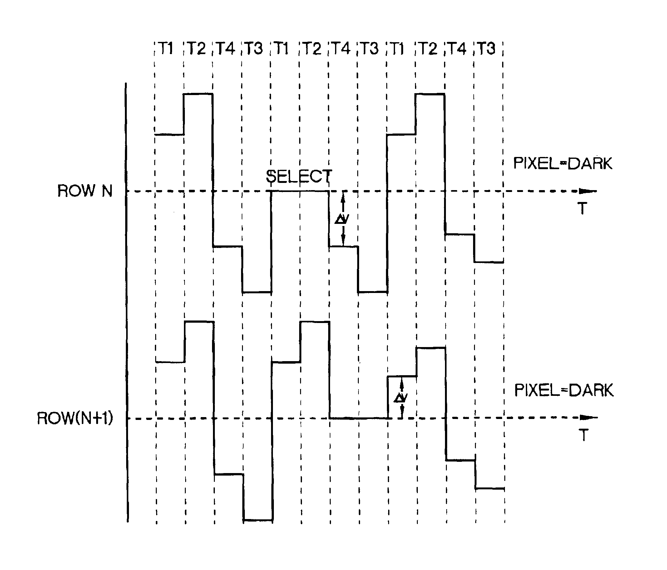
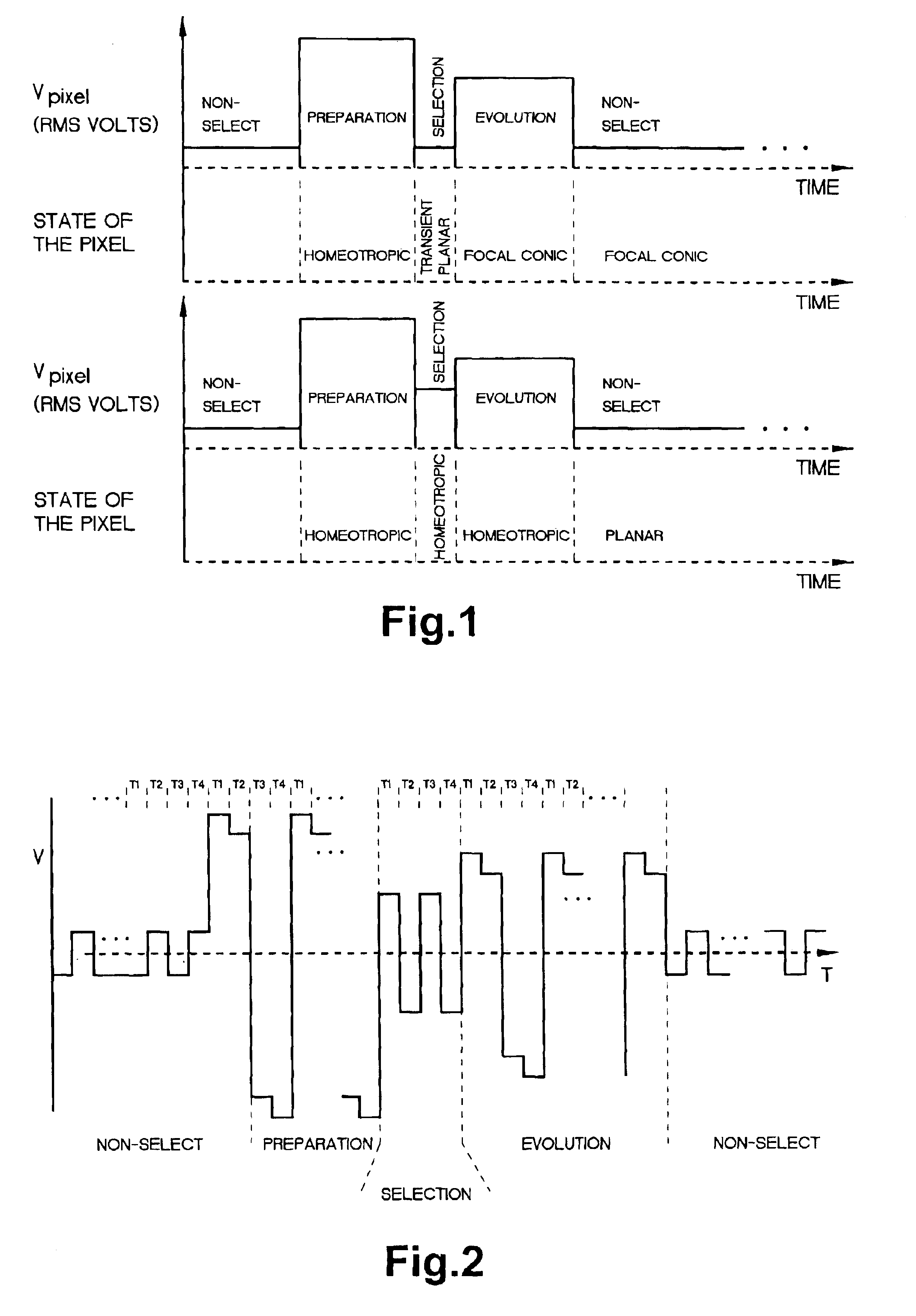
[0025]The following description will focus on the waveforms that make up the drive sequence for a bistable chiral nematic liquid crystal display (LCD) panel. For the purposes of this description, a simple “on” and “off” (binary) display scheme is discussed, but it is to be understood that the techniques described herein can be easily extended to gray scale addressing. The voltage waveforms described herein can be implemented using control electronics that are part of the display described in detail in the '840 patent. The reader is directed to that patent for the technical specifications of a LCD appropriate for implementation of the drive techniques described herein.

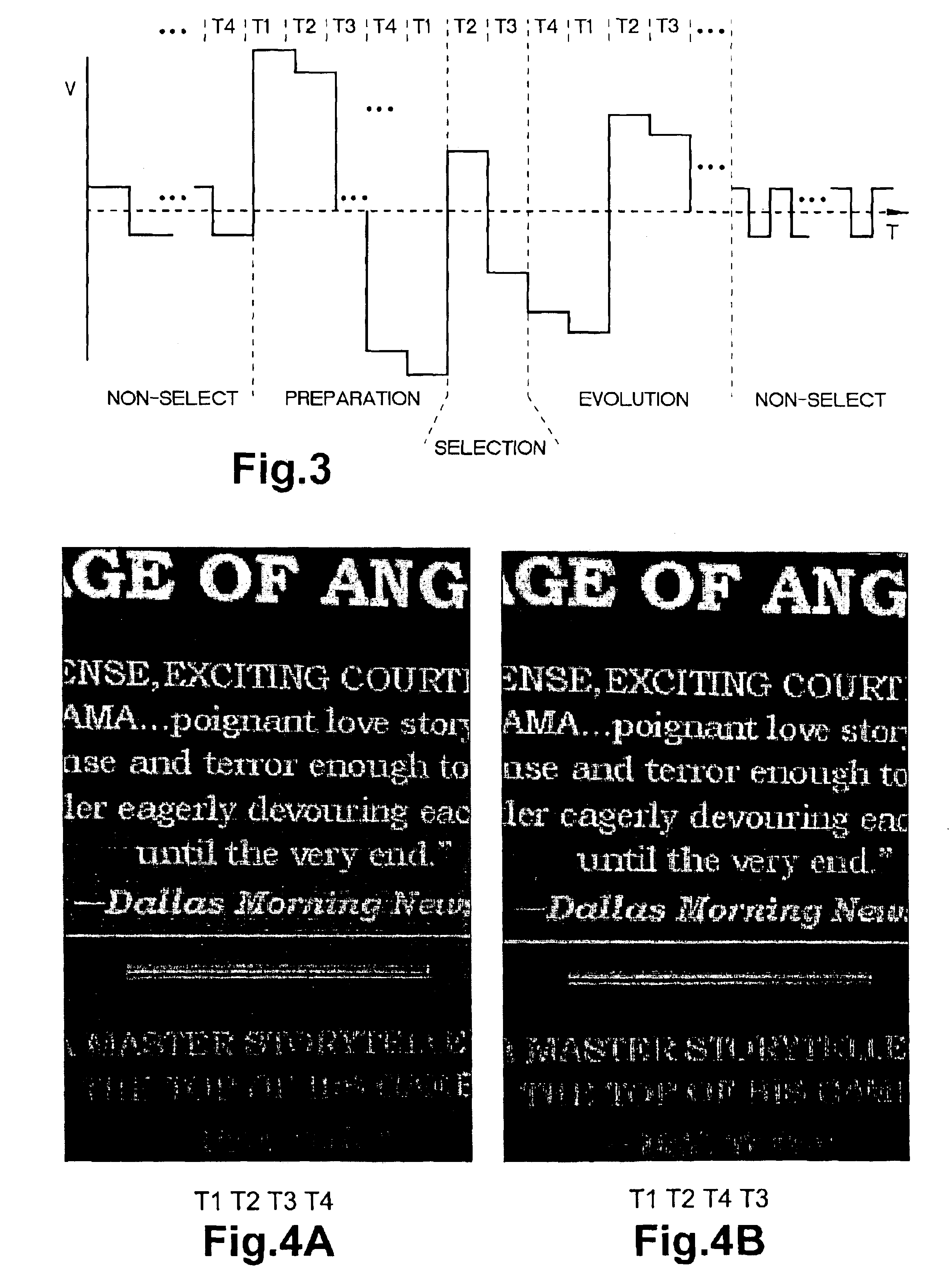
[0026]In experimental implementation of the dynamic drive scheme described in the '840 patent on a cholesteric liquid crystal display (Ch-LCD) panel, the inventor has observed an image anomaly known as “banding.” This phenomenon is most easily observed in the areas of the display that are uniform, such that all of the p...


PUM


Abstract

Reflective chiral nematic liquid crystal material is disposed between a first set of electrodes and a second set of electrodes arranged on opposed sides of the material to define a collection of pixels. Fast updating dynamic drive scheme is implemented by selectively applying an electric field via the electrodes through the pixels in four phases of energization: preparation, selection, evolution, and non-select. Each phase is made up of a series of voltages having varying amplitudes. The voltage waveform is for each phase controlled based on the selection phase to achieve image uniformity. For example, the evolution voltages that are established across adjacent pixels having the same final state have initial amplitudes that are equal for both pixels to increase image uniformity.

Description

FIELD OF THE INVENTION[0001]The present invention concerns a bistable display utilizing a chiral nematic liquid crystal material and an electronic drive system for activating the display using a sequence of voltages that enhances the appearance of the display.BACKGROUND ART[0002]Liquid crystals in flat panel displays have been used for many years, such as those used in watch faces or half page size displays for lap-top computers and the like.[0003]Chiral nematic liquid crystal (or Cholesteric Liquid Crystal Material) material can be energized by application of a voltage to exhibit different optical states. Four representative states (textures) for the chiral nematic material are homeotropic, planar, transient planar, and focal conic. When in the homeotropic state, the liquid crystal material is transparent to normally incident light impinging upon the liquid crystal material. When in the focal conic state, the liquid crystal material weakly scatters the light, although if the path l...

Claims


Application Information

Patent Timeline
Patent Type & Authority Patents(United States)
IPC IPC(8): G09G3/36
CPCG09G3/3629G09G2320/0233G09G2310/06G09G2300/0486
Inventor MILLER, IV, NICK MARTIN
Owner KENT DISPLAY SYST
Why Eureka
Try Eureka