Rotatable display fixing module

a fixing module and rotating technology, applied in the direction of portable computer details, instruments, electrical apparatus casings/cabinets/drawers, etc., can solve the problems of unstable working situation of display, unattractive appearance, and inability to provide all viewers with clear images on the display, etc., to achieve easy rotation and shake problems

Inactive Publication Date: 2005-06-28
QUANTA COMPUTER INC
View PDF16 Cites 53 Cited by
  • Summary
  • Abstract
  • Description
  • Claims
  • Application Information

AI Technical Summary

Benefits of technology

[0012]Hence, when the fixing switch rebounds up, the rotatable display fixing module according to the present invention locks the display to avoid turning left and right so that the shaking problem can be eliminated and the appearance thereof is more attractive. Furthermore, the fixing switch can cover the concave hole to prevent foreign objects from dropping into the concave hole so as to protect the rotating mechanism from damage. The display can easily rotate on the first and second rotational device when the fixing switch is pressed down and together with the auxiliary stud.

Problems solved by technology

However, due to a conventional restricted display angle, the notebook computer cannot provide all viewers with clear images on the display.
Because the display is able to rotate, not fixed, the display may shake when the tablet PC is working so that the display is in an unstable working situation.
The concave hole may induce an unattractive appearance and further allows foreign objects to drop into the concave hole to interfere with the rotation of the rotating mechanism and even to damage the rotating mechanism.

Method used


Image

  • Rotatable display fixing module
  • Rotatable display fixing module
  • Rotatable display fixing module

Examples


Embodiment Construction

[0018]The following description is of the best presently contemplated mode of carrying out the present invention. This description is not to be taken in a limiting sense but is made merely for the purpose of describing the general principles of the invention. The scope of the invention should be determined by referencing the appended claims.

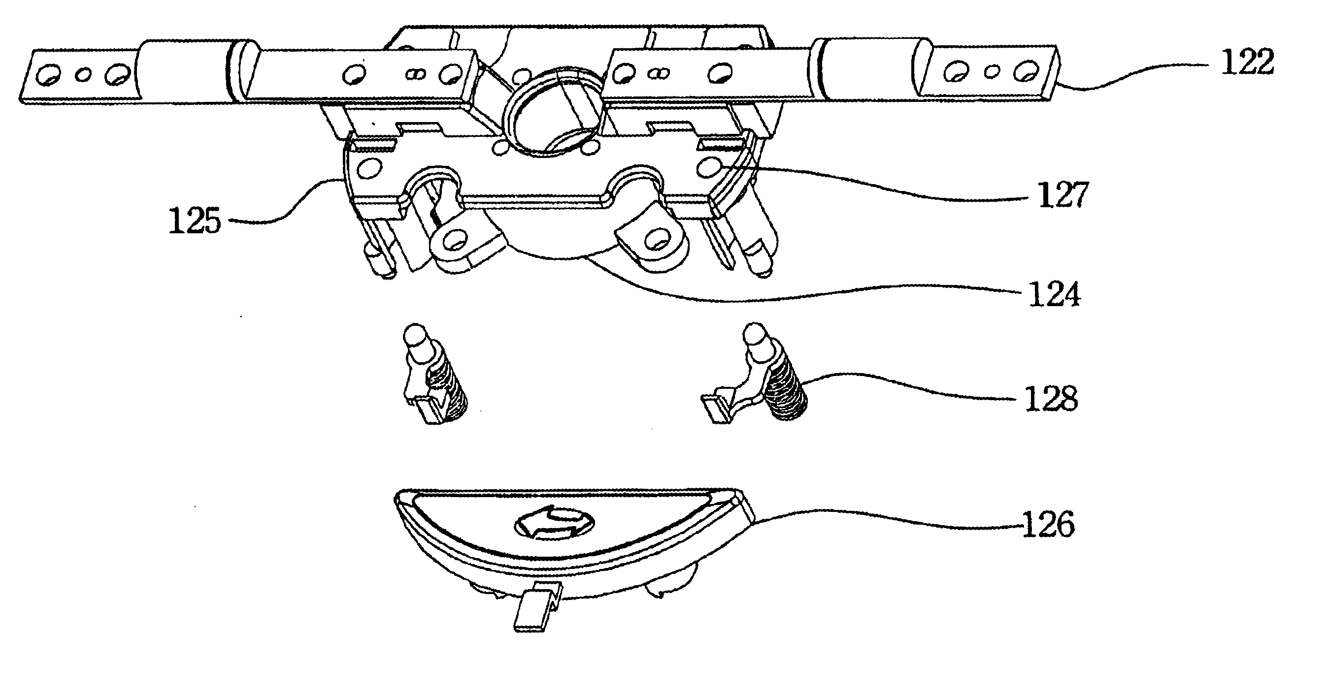
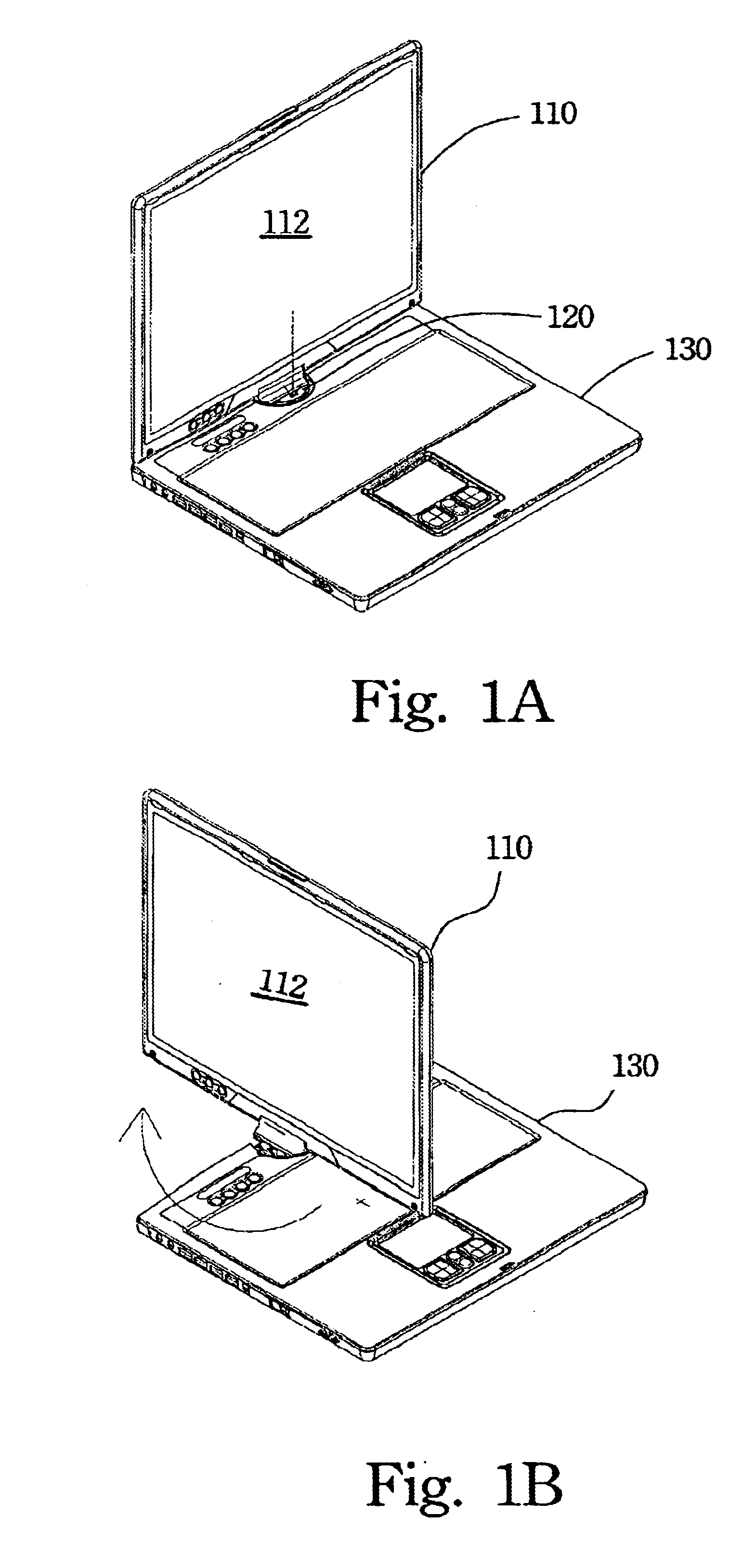
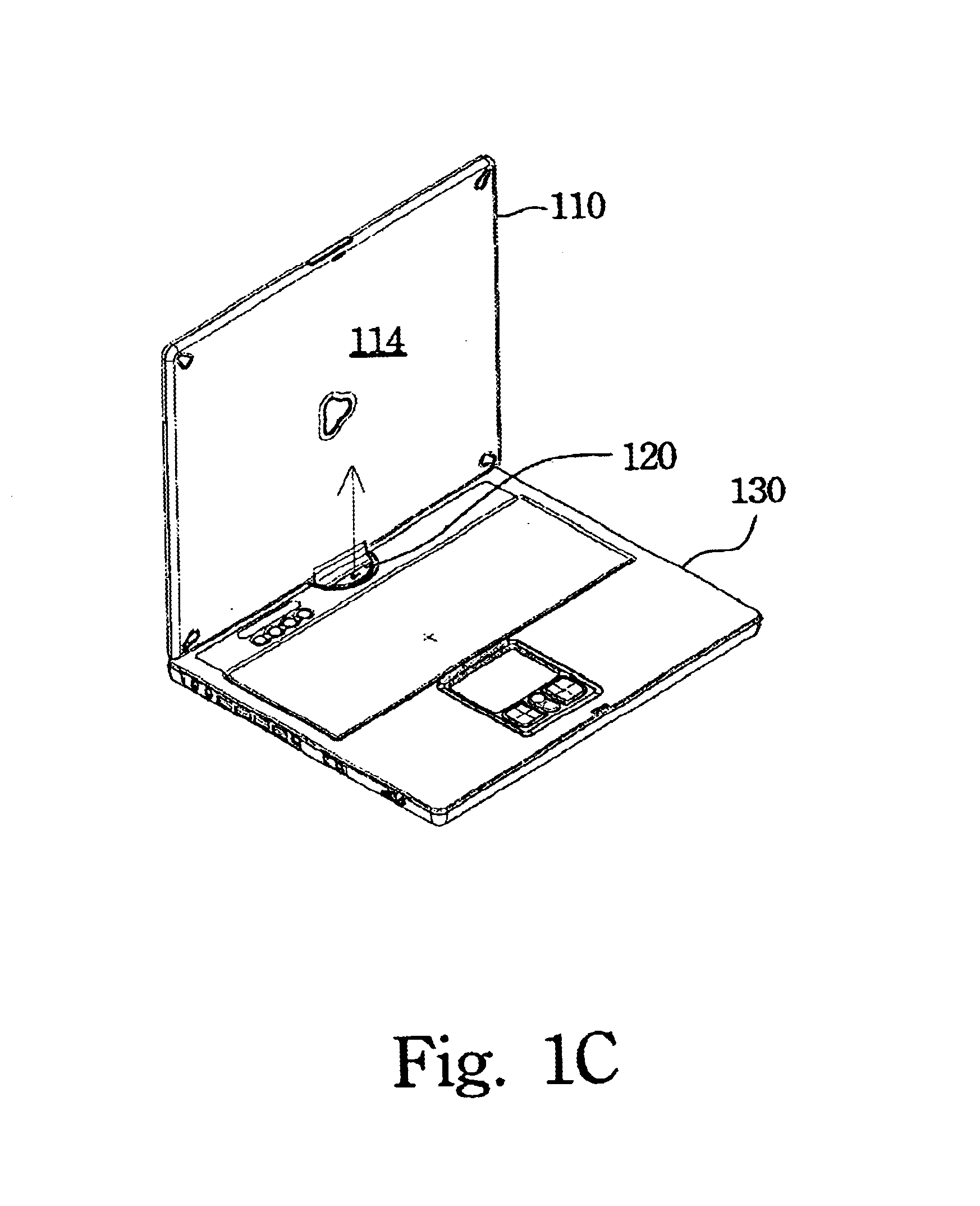
[0019]FIG. 1A to FIG. 1C illustrate a display with a rotatable display fixing module of a preferred embodiment according to the present invention. FIG. 1A illustrates the display as being just opened from a base of a notebook computer. FIG. 1B illustrates the display rotated about 90 degrees from the original position. FIG. 1C illustrates the display rotated about 180 degrees from the original position. Referring to FIGS. 1A to 1C, the notebook computer includes a display 110, a rotatable display fixing module 120, and a base 130. The display 10 further includes a display panel 112 on the front side of the display 110 and a display back cover 114...


PUM


Abstract

A rotatable display fixing module is described. The rotatable display fixing module has a first rotational device, a second rotational device, a fixing switch and an auxiliary fixing stud. The first rotational device rotatably connects with a display and the second rotational device. The fixing switch and the auxiliary fixing stud rebound up to fix the second rotational device at predetermined angles and the auxiliary fixing stud passes through a fixing hole on a rotational element of the second rotational device. The display can therefore rotate on the first rotational device only. When the fixing switch and the auxiliary fixing stud are pressed, the display can rotate on the first rotational device and the second rotational device.

Description

FIELD OF THE INVENTION[0001]The present invention relates to a rotatable display fixing module and especially to a rotatable display fixing module for notebook computer.BACKGROUND OF THE INVENTION[0002]Recently, liquid crystal displays (LCD) have been widely applied in electrical products, due to the rapid progress of optical technology and semiconductor technology. Moreover, with the advantages of high image quality, compact size, light weight, low driving voltage, and low power consumption, LCDs have been introduced into portable computers, personal digital assistants, color televisions, and are gradually replacing the cathode ray tubes (CRT) used in conventional displays. LCDs are becoming the mainstream display apparatus.[0003]A conventional display of a notebook computer is disposed in the upper cover of the notebook computer. The display demonstrates information and images thereon when the upper cover of the notebook computer is opened. The upper cover and a base of the notebo...

Claims


Application Information

Patent Timeline
Patent Type & Authority Patents(United States)
IPC IPC(8): G06F1/16
CPCG06F1/162G06F1/1681G06F1/1679Y10S248/917
Inventor CHEN, WEN-HSIANGYANG, KUO-CHANGCHANG, JUNG-WEN
Owner QUANTA COMPUTER INC
Why Eureka
Try Eureka