Synchronous rectifier control circuit

Inactive Publication Date: 2005-06-28
ARTESYN TECH
View PDF25 Cites 14 Cited by
  • Summary
  • Abstract
  • Description
  • Claims
  • Application Information

AI Technical Summary

Benefits of technology

[0008]According to another embodiment, the method includes differentiating the output voltage of the converter and controlling conduction of the synchronous rectifier in proportion to the differentiated output voltage. The method may also include increasing the rate of increase of a voltage level of a control signal to the synchronous rectifier if the output voltage is monotonic and rising. In addition, the method may further include decreasing the rate of increase of the voltage level of the control signal to the syn

Problems solved by technology

In this configuration, large circulating currents will flow if the two converters are not perfectl

Method used


Image

  • Synchronous rectifier control circuit
  • Synchronous rectifier control circuit
  • Synchronous rectifier control circuit

Examples


Example

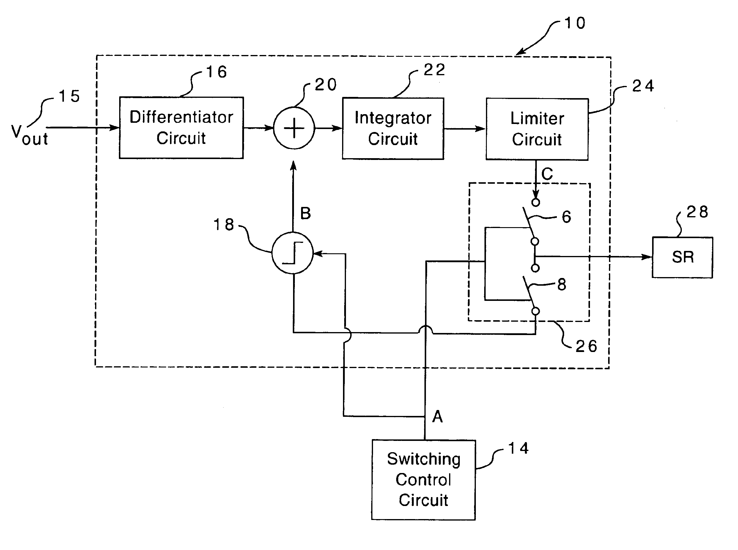
[0015]It is to be understood that the figures and descriptions of the present invention have been simplified to illustrate elements that are relevant for a clear understanding of the present invention, while eliminating, for purposes of clarity, other elements of a conventional power converter. For example, certain power converters require a transformer reset mechanism. However, such reset mechanisms are not described herein. Those of ordinary skill in the art will recognize, however, that these and other elements may be desirable in a typical power converter. However, because such elements are well known in the art, and because they do not facilitate a better understanding of the present invention, a discussion of such elements is not provided herein.

[0016]All circuit components are assumed to be ideal for the purpose of describing the present invention. In addition, as used herein, the term “ON” is used synonymously with “closed,” and the term “OFF” is used synonymously with “open...


PUM


Abstract

A synchronous rectifier control circuit for controlling a synchronous rectifier of a power converter is disclosed. According to one embodiment, the control circuit includes a differentiator circuit responsive to the output voltage of the power converter. The control circuit also includes a summing circuit responsive to an output of the differentiator circuit and a step function signal. The control circuit further includes an integrator circuit responsive to an output of the summing circuit. In addition, the control circuit includes a gate drive circuit responsive to an output of the integrator circuit and a switching signal that controls a primary switch of the converter. The gate drive circuit also includes an output terminal for coupling to a control terminal of the synchronous rectifier.

Description

CROSS-REFERENCE TO RELATED APPLICATIONS[0001]This application claims priority under 35 U.S.C. §119 to U.S. provisional patent application Ser. No. 60 / 407,903, filed Sep. 3, 2002, which is incorporated herein by reference.BACKGROUND OF THE INVENTION[0002]The use of synchronous rectifiers (SRs) is well established in DC-DC power converters to improve the conduction loss of the output stage. When synchronous rectification is applied to a topology, the resultant power converter is transformed into a two-quadrant converter. As such, the converter can sink and source current.[0003]If a back biased load is applied to the output of a power converter during the startup phase, a condition is created that is analogous to placing two converters in parallel. In this configuration, large circulating currents will flow if the two converters are not perfectly matched in voltage and thus have a negative effect on the load and or the power converter system. Therefore, there exists a need in the art f...

Claims


Application Information

Patent Timeline
IPC IPC(8): H02M3/335H02M3/24
CPCH02M3/33592Y02B70/1475Y02B70/10
Inventor PERRY, MARTYPOYNTON, IAN
Owner ARTESYN TECH
Why Eureka
Try Eureka