Lance for injecting fluids for uniform diffusion within a volume

Inactive Publication Date: 2005-07-05
AIR LIQUIDE AMERICA INC +1
View PDF13 Cites 0 Cited by
  • Summary
  • Abstract
  • Description
  • Claims
  • Application Information

AI Technical Summary

Benefits of technology

[0008]It is a further object of the present invention to ensure substantially complete and uniform diffusion of fluid over the target area within the system volume while minimizing the amount of fluid injected into the system volume.
[0013]The lance design and corresponding methods facilitate the injection of one or more fluids at a uniform flow rate into an enclosed volume and over a predefined target area, while minimizing the amount of fluid required to encompass the target area.

Problems solved by technology

In order to ensure a sufficient amount of oxygen is injected within the boiler during system operation, it is often necessary to inject excessive amounts of oxygen from the lance, which results in increased operational costs.

Method used


Image

  • Lance for injecting fluids for uniform diffusion within a volume
  • Lance for injecting fluids for uniform diffusion within a volume
  • Lance for injecting fluids for uniform diffusion within a volume

Examples


Embodiment Construction

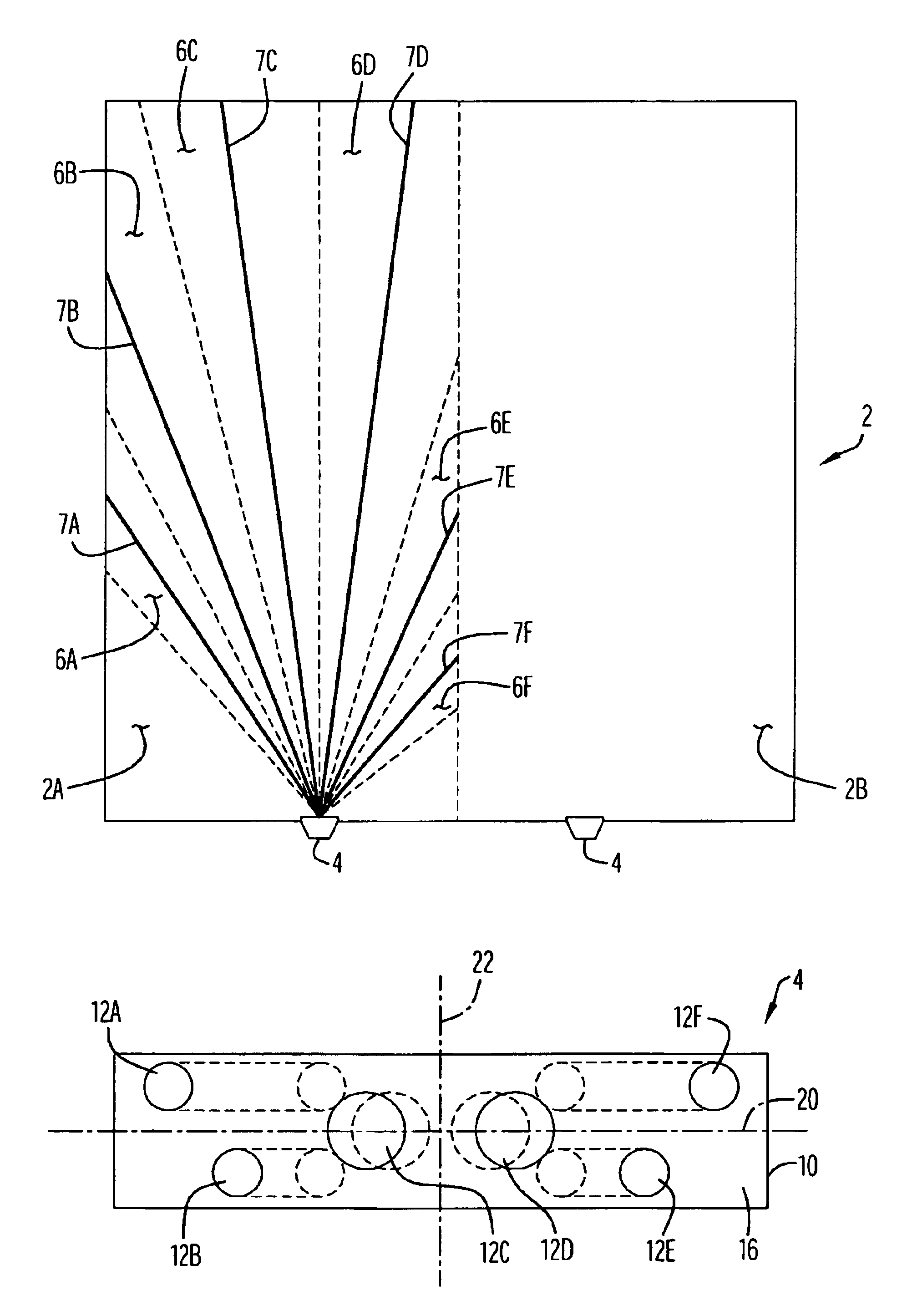
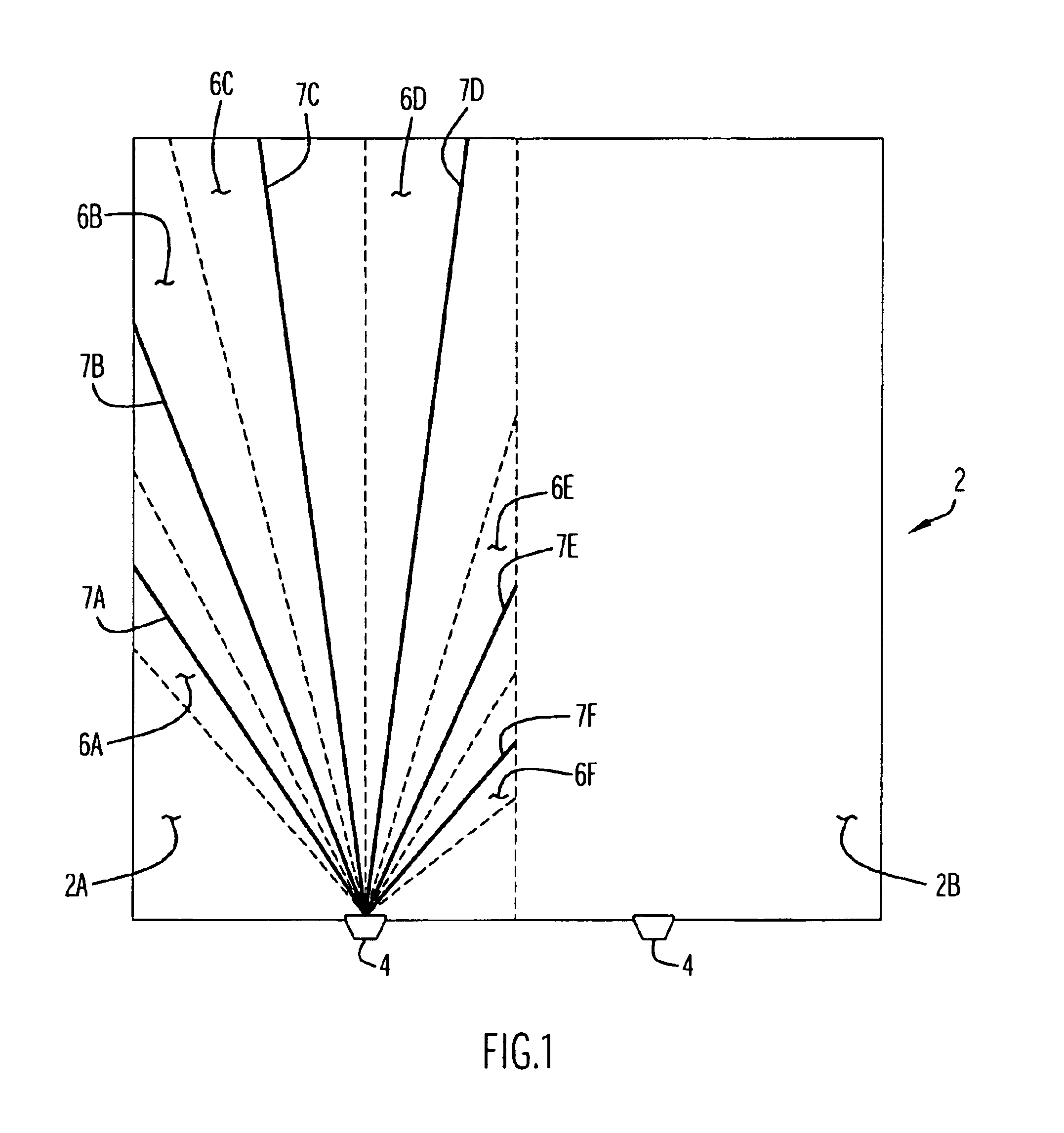
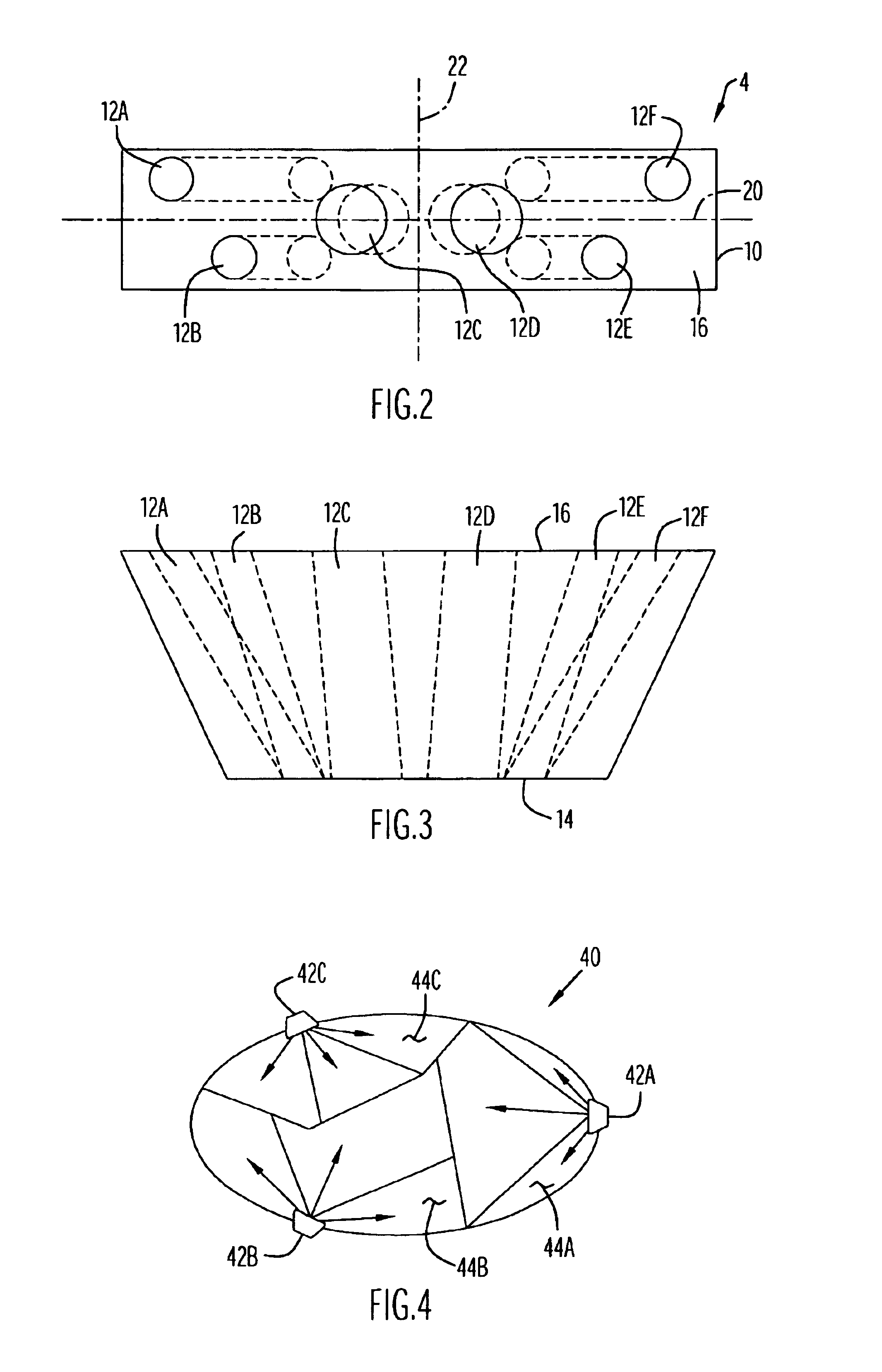
[0019]An injection lance in accordance with the present invention includes a plurality of injection ports or channels (i.e., two or more) to deliver one or more fluids into a boiler, furnace or other system for diffusion within a selected or predefined target area of the system. Any suitable number of lances (e.g., one or more) may be utilized with the system, with each lance including a selected number of fluid injection channels extending through the lance between inlet and outlet sides of the lance. The injection channels of the lance are preferably oriented in a non-parallel manner with respect to each other, with two or more channels diverging away from a central portion of the lance as the channels extend from the inlet side to the outlet side of the lance. The orientation of injection channels in this manner facilitates injection of fluid streams from the injection channels into the system in a spread or fan-shaped manner to cover the target area associated with the lance wit...


PUM


Abstract

An injection lance for injecting a fluid over a predefined target area within a system includes a support block with an inlet side and an outlet side. A plurality of channels are disposed non-parallel with respect to each other within the support block and extend between the inlet and outlet sides of the support block so as to receive fluid at the inlet side and deliver fluid through the support block for injection from the outlet side of the support block over the target area. At least two channels extend from the inlet side toward the outlet side in a direction away from a central axis of the support block, where the central axis intersects the outlet side. The target area includes a plurality of consecutively aligned sectors, and the channels are oriented within the support block so that a central axis of a fluid stream injected from each channel over the target area is centered between longitudinal boundaries defined by a respective sector.

Description

CROSS REFERENCE TO RELATED APPLICATIONS[0001]This application claims priority from U.S. Provisional Patent Application Ser. No. 60 / 425,827, entitled “Smart Lance Concept and Design”, and filed Nov. 13, 2002. The disclosure of this provisional patent application is incorporated herein by reference in its entirety.BACKGROUND OF THE INVENTION[0002]1. Technical Field[0003]The present invention pertains to injection lances for delivering fluids into high volumes such as boilers.[0004]2. Discussion of the Related Art[0005]Injection lances are utilized in boilers, furnaces and other systems to deliver one or more fluids, typically gases, at selected concentrations and flow rates to one or more selected areas within the system. In particular, injection lances are utilized in boilers to deliver oxygen into the boiler as an oxidant for mixing and reaction with fuels (e.g., coal, natural gas, oil, etc.) disposed and / or flowing within the boiler. In order to ensure a sufficient amount of oxygen...

Claims


Application Information

Patent Timeline
IPC IPC(8): A47L5/14A47L5/12B08B3/00F22B37/00F23D14/48F22B37/48F27B3/22F27B3/10B65B1/04F27B
CPCF27B3/225
Inventor MARIN, OVIDIUMACADAM, SCOTTBUGEAT, BENJAMINCHATEL-PELAGE, FABIENNE
Owner AIR LIQUIDE AMERICA INC
Why Eureka
Try Eureka