

Torque sensing apparatus and method
- Summary
- Abstract
- Description
- Claims
- Application Information
AI Technical Summary
Benefits of technology
Problems solved by technology
Method used
Image

Examples
first embodiment
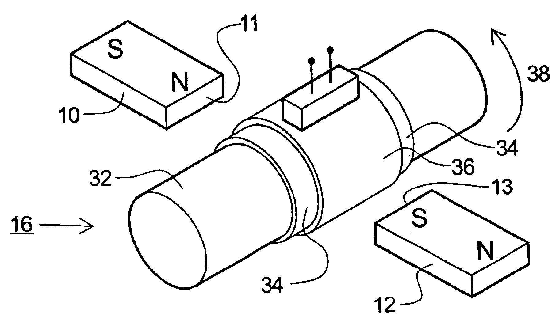
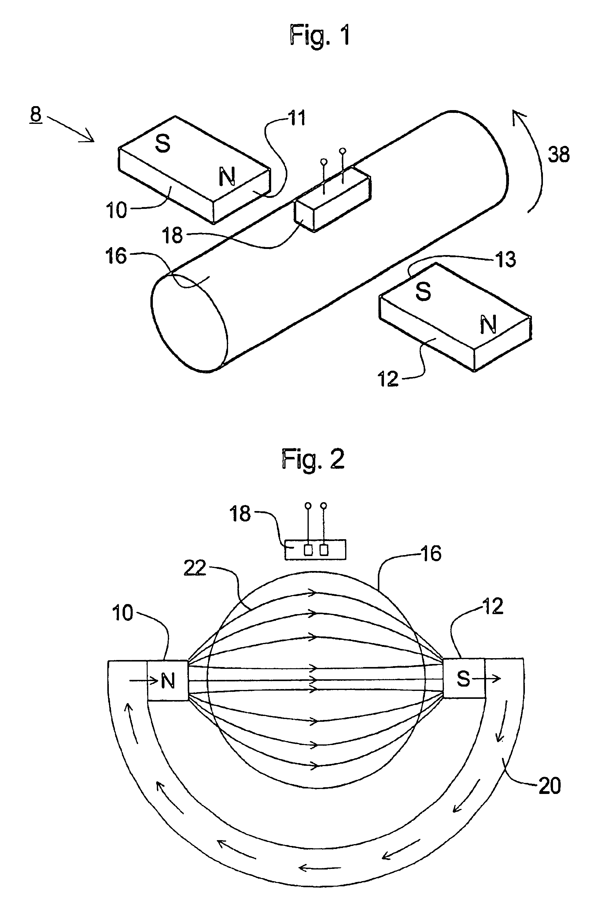
[0042]FIG. 1 is a schematic diagram of a magnetostrictive sensor 8 according to the invention. The magnetostrictive sensor 8 comprises a shaft 16 that can be subjected to a torque 38 to be sensed, as illustrated by an arrow in the figure. The shaft 16 is made of a magnetostrictive material, but is not itself permanently magnetized (in contrast to the prior art designs referred to in the introduction). Instead of permanently magnetizing the shaft, the shaft 16 is magnetized in situ by an external magnetic field generated by a pair of permanent magnets 10 and 12.
[0043]The shaft 16 is made of the magnetostrictive material “Terfenol-D” which has a very high magnetostrictive coefficient λ=ΔL / L of the order of 2000×10−6. Generally, materials with magnetostrictive coefficients of at least 20×10−6 are preferred for the shaft, although a shaft made of material with a lower magnetostrictive coefficient will still function.
[0044]Some examples of other suitable materials for the shaft are:
[0045...
second embodiment
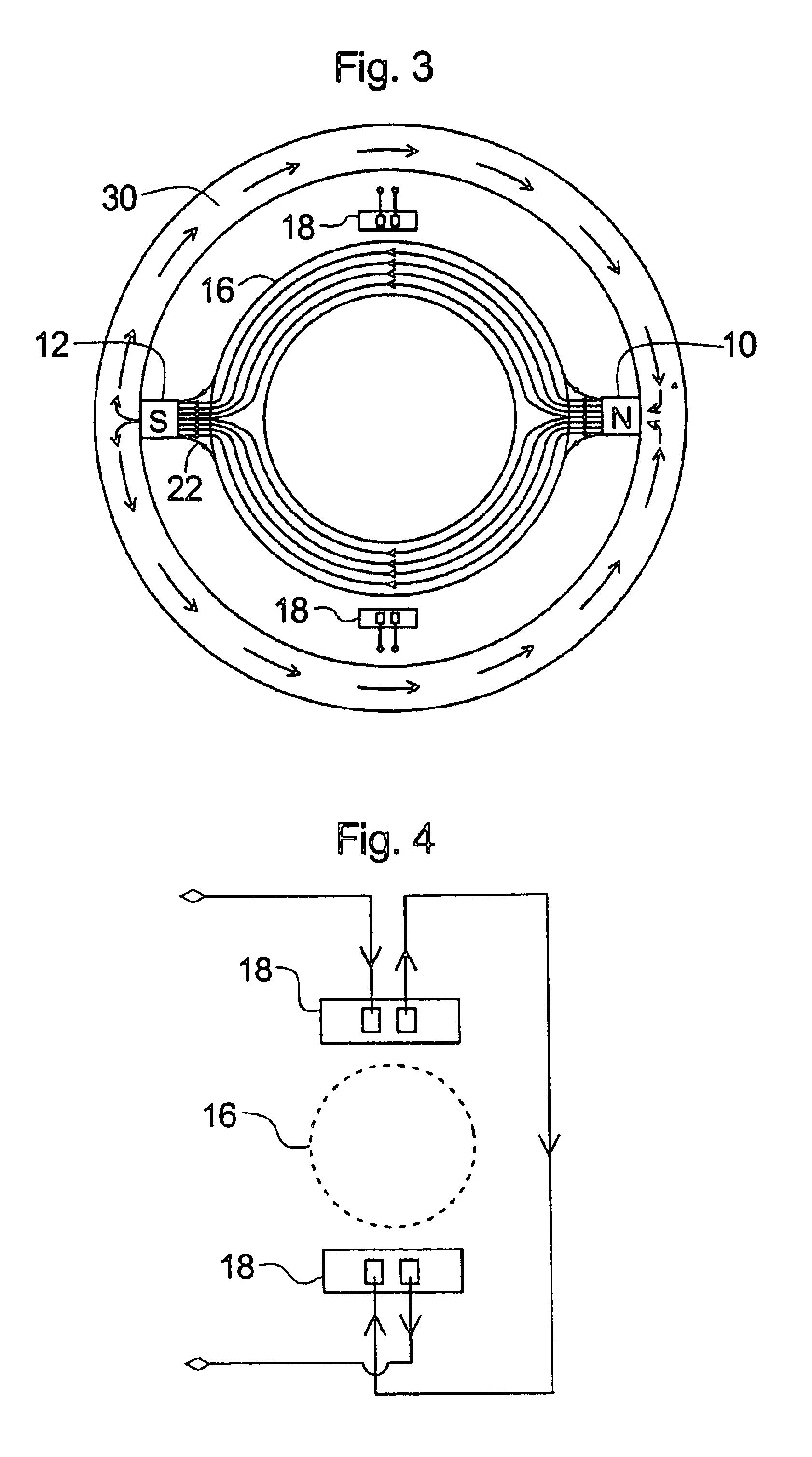
[0055]FIG. 4 shows the electrical interconnections of the two flux detectors 18 of the As illustrated, the flux detectors 18 are wired in series. Moreover, the connections are such that the current induced by the magnetic flux in the two flux detectors sums together. This is achieved when terminals of like polarity are arranged circumferentially adjacent to each other as viewed around the outer surface of the shaft 16. This connection scheme is geometrically opposite to what would be done with the prior art, in which terminals of opposite polarity in circumferentially adjacent detectors would be connected together. This is because, in the prior art, the magnetic flux flows unidirectionally around the circumference of the shaft, for example clockwise, as a result of the unidirectional permanent magnetic poling. By contrast, in the present case, there are two circumferential field components one flowing clockwise and the other anti-clockwise around the shaft, as a result of the magne...
fifth embodiment
[0059]FIG. 7 shows in cross-section a torque sensor according to the invention. The torque sensor 8 comprises four permanent magnets 10, 12, 10′ and 12′ arranged radially within and held in place by a ring 30 which is made of a magnetic material to give closure to the magnetic field 22 generated by the permanent magnets. The magnets are arranged so that circumferentially adjacent magnets have opposite poles 11, 13, 11′, 13′ facing the shaft 16 in a—sequence. In addition, the magnets are arranged at equal angular intervals of 90°, although this angular spacing is not critical and could be varied. With this arrangement, the magnetic flux penetrates the shaft 16 predominantly in its radially outer regions, thus achieving similar advantages to the above-described embodiments where flux is excluded from the central region either by use of a hollow shaft or provision of a flux excluding non-magnetic layer. The present embodiment has the additional advantage that the desired concentration ...
PUM
 Abstract
Description
Claims
Application Information