Printing press with a temperature control unit for a plate cylinder

a technology of temperature control unit and printing press, which is applied in printing presses, rotary letterpress machines, printing, etc., to achieve the temperature control of the plate surface in a precise manner, and efficiently utilize the plate-replacement spa

Inactive Publication Date: 2005-07-05
RYOBI
View PDF6 Cites 3 Cited by
  • Summary
  • Abstract
  • Description
  • Claims
  • Application Information

AI Technical Summary

Benefits of technology

[0019]According to another aspect of the present invention, there is provided a printing press with a temperature control unit for controlling the temperature of a surface of a printing plate mounted on a plate cylinder by feeding air onto the plate cylinder, in which the plate cylinder is designed so that plural printing plates are mounted thereon. The printing press includes an image-forming unit disposed in proximity to the plate cylinder so as to form an image on each of the plural printing plates. A plate-replacement space is provided in a certain region around the plate cylinder for replacement of a printing plate mounted on the plate cylinder with a new one introduced from the outside of the printing press. The temperature control unit is designed to be selectively shifted between a temperature control mode and a space opening mode. The temperature control mode enables air to be fed through the plate-replacement space onto the plate cylinder. The space opening mode makes the plate-replacement space open to the outside of the printing press so that the replacement of a printing plate can be done.
[0020]Generally, when plural printing plates are mounted on a plate cylinder, the same number of ink units are correspondingly disposed for these printing plates for supplying ink thereon. When an image-forming unit is to be provided around the plate cylinder in addition to the ink units, it is very difficult to secure a space exclusively used for airflow onto the plate cylinder therearound. However, according to the printing press of the present invention, it is not necessary to separately provide a space exclusively used for airflow onto the printing plate, since the feeding of air onto the plate cylinder is achieved by efficiently utilizing the plate-replacement space. In addition, this utilization of the plate-replacement space makes it possible to prevent various units and parts such as ink units and an image-forming unit located around the plate cylinder from blocking airflow onto the plate cylinder so that air can be securely fed onto the plate cylinder, thus achieving the temperature control of the plate surface in precise manner.

Problems solved by technology

In addition, various constitutional members or parts provided around the plate cylinder are unlikely to block airflow, since air is fed by utilizing the printing plate-replacement space.

Method used


Image

  • Printing press with a temperature control unit for a plate cylinder
  • Printing press with a temperature control unit for a plate cylinder
  • Printing press with a temperature control unit for a plate cylinder

Examples


Embodiment Construction

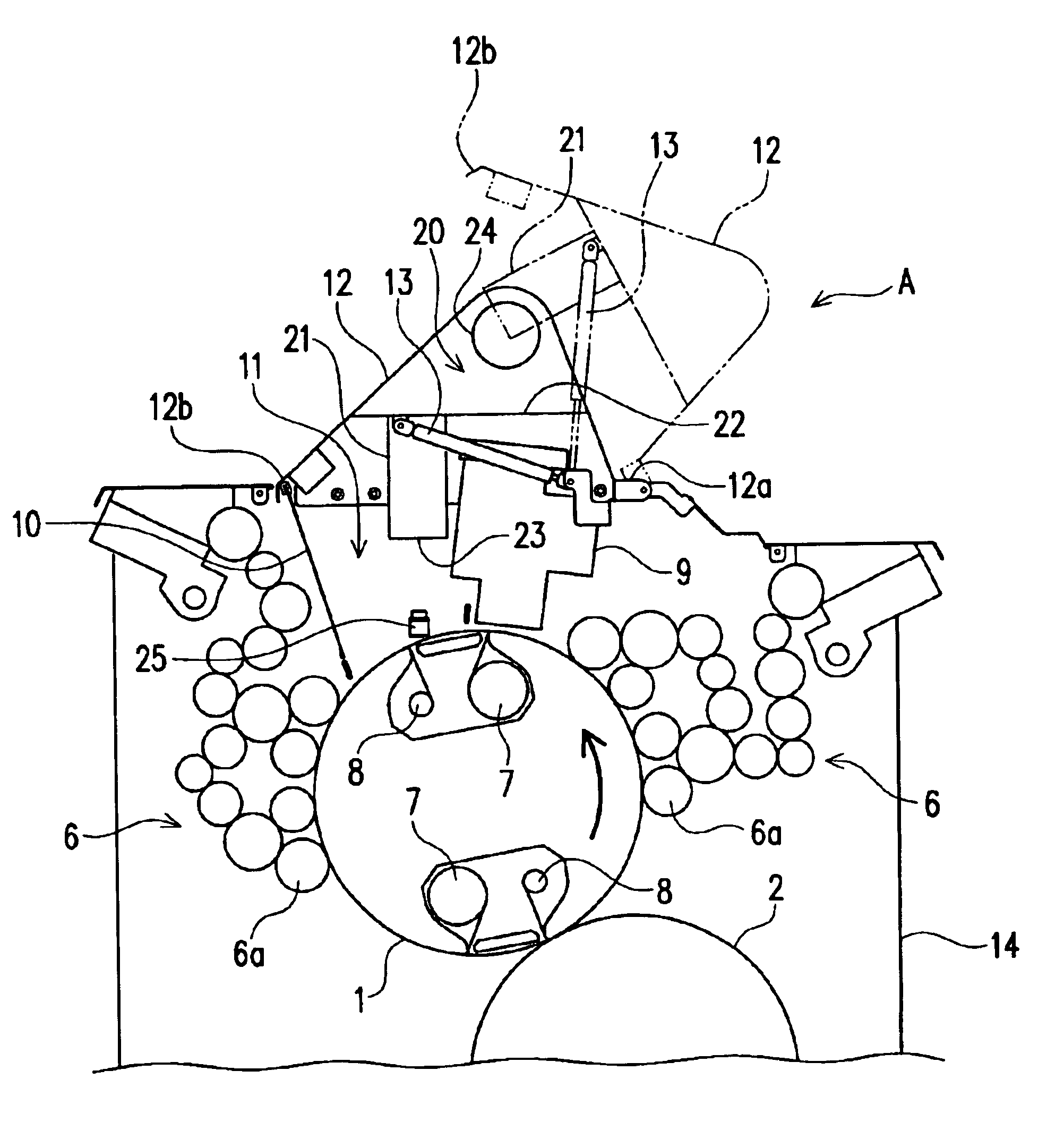
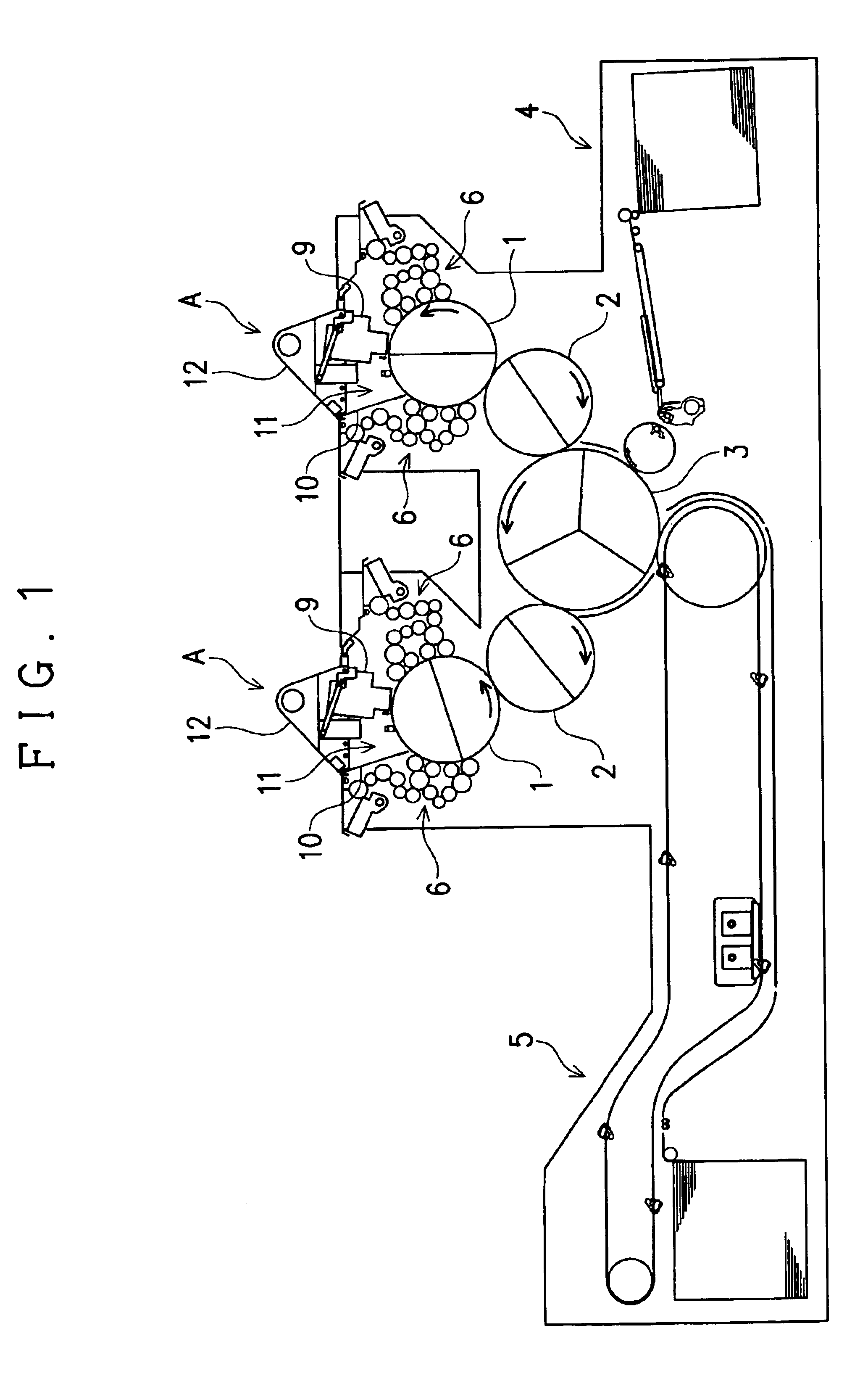
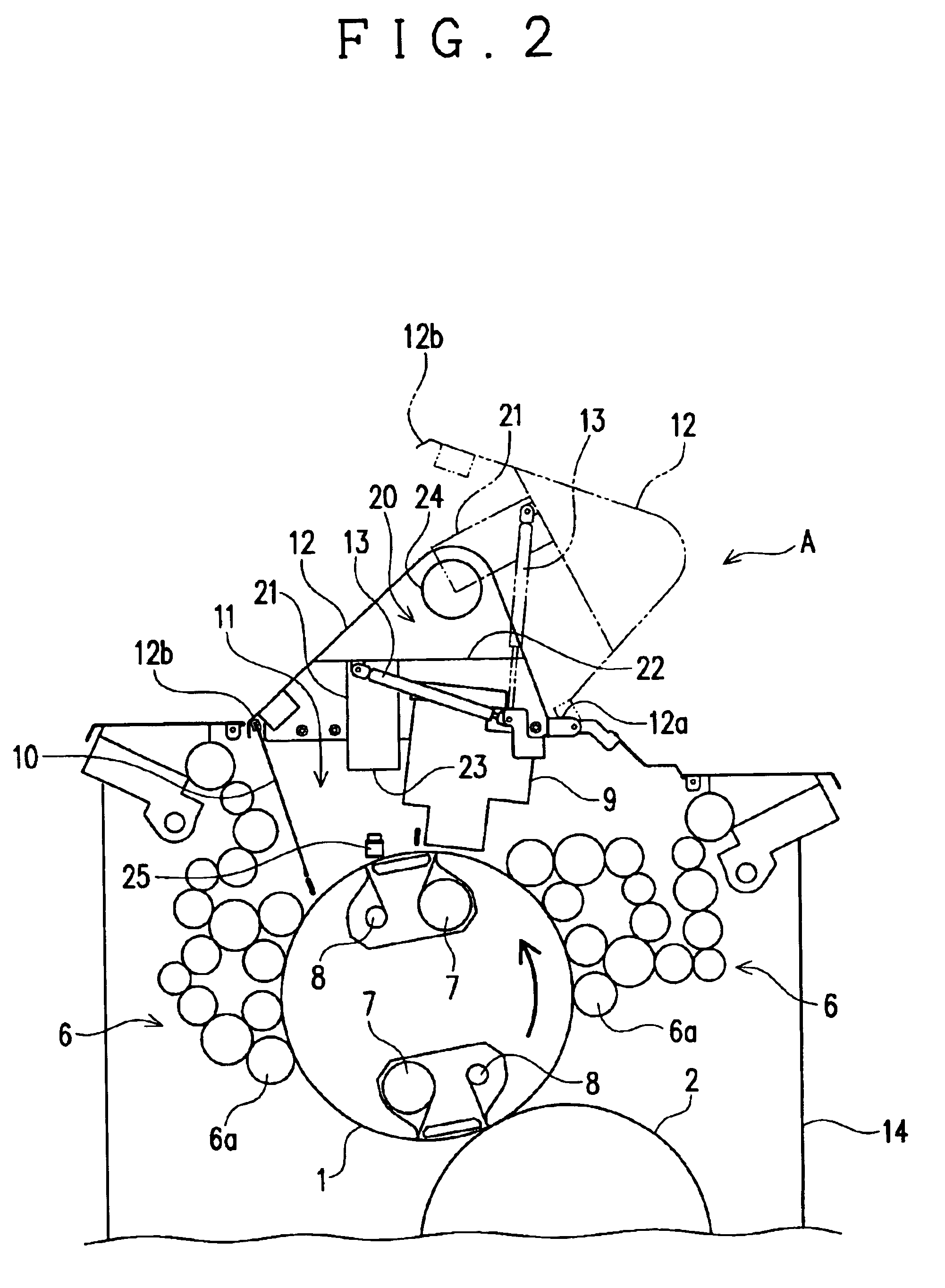
[0032]An embodiment of the printing press with the temperature control unit for the plate surface according to the present invention will be herein described with reference to FIGS. 1 to 4. The description will be first made for the printing press that includes a plate-surface temperature control device A for controlling the temperature of the plate surface by feeding air onto a plate cylinder 1.

[0033]The printing press of this embodiment is a four color printing press that has four plate surfaces in total. Specifically, two pairs, each pair including the plate cylinder 1 and a blanket cylinder 2, are provided for an impression cylinder 3 according to the cylinder arrangement of the printing press of this embodiment. The impression cylinder 3 is a triple-diameter cylinder, while each of the plate cylinder 1 and the blanket cylinder 2 is a double-diameter cylinder that has two plate surfaces. Sheets of paper fed from a sheet-feeding unit 4 and placed on the impression cylinder 3 each...


PUM


Abstract

A printing press is provided with a temperature control unit for controlling the temperature of a surface of a printing plate mounted on a plate cylinder by feeding air onto the plate cylinder. A plate-replacement space is provided in a certain region around the plate cylinder for replacement of a printing plate mounted on the plate cylinder with a new one introduced from the outside of the printing press. The temperature control unit is designed to be selectively shifted between a temperature control mode and a space opening mode, in which the temperature control mode enables air to be fed through the plate-replacement space onto the plate cylinder, and the space opening mode makes the plate-replacement space open to the outside of the printing press so that the replacement of a printing plate can be done.

Description

CROSS REFERENCE TO RELATED APPLICATION[0001]This application claims priority from Japanese Patent Application No. 2003-007084, which is incorporated herein by reference.BACKGROUND OF THE INVENTION[0002]1. Field of the Invention[0003]The present invention relates to a printing press with a temperature control unit for a plate cylinder and more particularly for a surface of each printing plate mounted on the plate cylinder.[0004]2. Related Art[0005]A printing press constructed having a plate cylinder on which printing plates are mounted is equipped with an ink unit for supplying ink onto each printing plate. The ink unit transfers ink from an ink fountain through a number of ink rollers, and finally onto the surface of each printing plate mounted on the plate cylinder through an ink-applying roller (a foam roller) of these ink rollers. As used throughout the description, by a surface of the plate cylinder or a plate surface is meant the circumference of the plate cylinder with a singl...

Claims


Application Information

Patent Timeline
Patent Type & Authority Patents(United States)
IPC IPC(8): B41F13/22B41F13/08B41F13/00B41F33/00
CPCB41F13/22B41P2227/70
Inventor AOYAMA, HIDEOBABA, HIDEKATSU
Owner RYOBI
Why Eureka
Try Eureka