Hammer

Inactive Publication Date: 2005-07-05
BLACK & DECKER INC
View PDF33 Cites 39 Cited by
  • Summary
  • Abstract
  • Description
  • Claims
  • Application Information

AI Technical Summary

Benefits of technology

[0007]The present invention aims to provide a hammer arrangement with an effective design of spindle lock arrangement for hammering mode which enables automatic engagement of a spindle drive teeth with a set of spindle lock teeth, without a user having to manually adjust the rotational position of the spindle.
[0016]Thus, an improved spindle lock arrangement is provided in which a resilient synchronising element engages the set of teeth as the hammer is moved towards its second mode. The synchronising element is able to deform or move in order to engage the set of teeth and then, because it is resilient, the synchronising element then moves back to its original position or state in order to rotate the set of teeth into a meshing alignment with the spindle lock tooth or teeth. Therefore, as the hammer is moved into its second mode the set of teeth are automatically aligned with the spindle lock tooth or teeth. Accordingly, the user will not generally need to manually rotate the spindle in order to bring the teeth into meshing alignment. As soon as the set of teeth and the spindle lock tooth or teeth are in meshing engagement the spindle is locked in the hammer housing against rotation and second mode of the hammer is achieved.
[0017]To facilitate the synchronisation of the set of teeth by engagement with the synchronising element the teeth are preferably chamfered. The teeth are chamfered so that they taper to a reduced width towards their ends. The chamfering of the teeth results in adjacent teeth having facing surfaces which slope away from each other. The synchronising element engages one or more of the sloping surfaces, and a biasing force from the synchronising element due to the resilient characteristic of the synchronising element causes the synchronising element to move towards the root of each tooth along the sloping surface and so push the tooth to one side, causing the set of teeth to move into a position in which they are meshingly aligned with the spindle lock tooth or teeth. To achieve this the synchronising element is located on the spindle lock arrangement so as to be aligned with a position of a spindle lock tooth or a position where an additional spindle lock tooth suitable for engaging the set of teeth would be located, in addition to the spindle lock tooth or teeth.

Problems solved by technology

One problem with such mode change mechanisms is gear synchronisation.

Method used


Image

  • Hammer
  • Hammer
  • Hammer

Examples


first embodiment

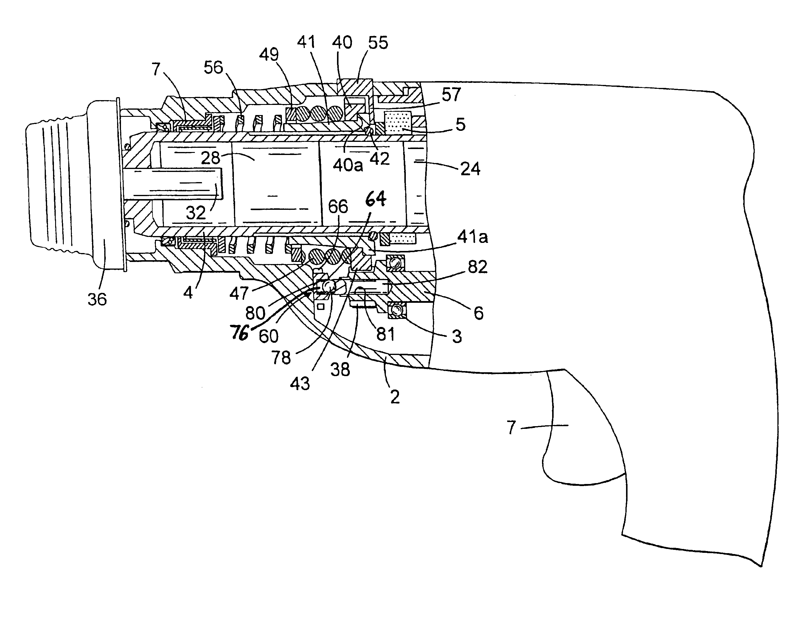
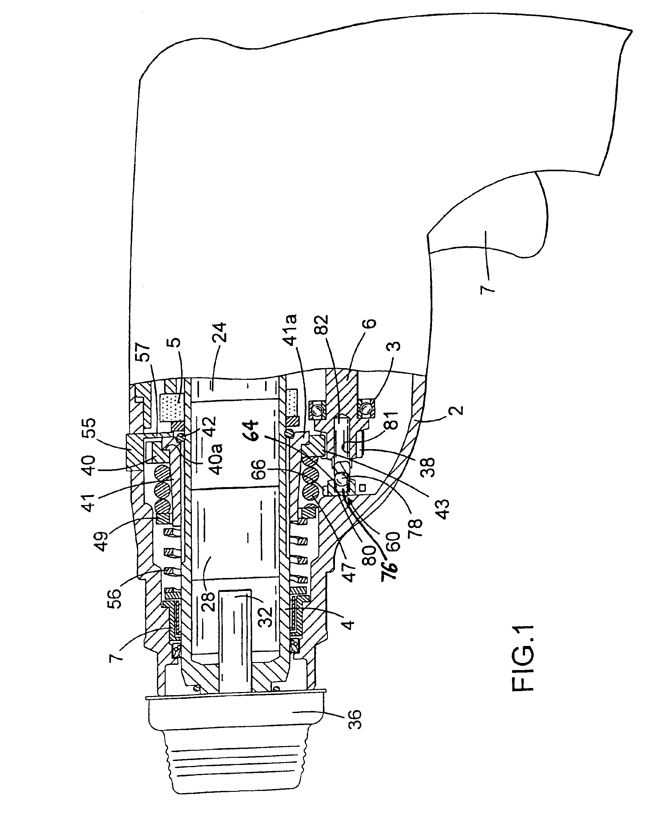
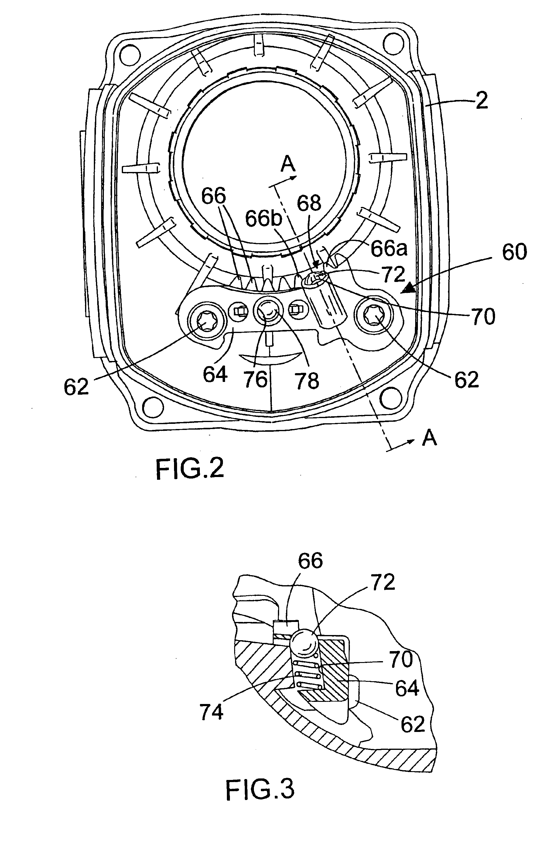
[0034]the spindle lock arrangement is shown in FIGS. 2 and 3 and is fixed within the hammer housing (2) in the position shown in FIG. 1, at the forward end of the intermediate shaft (6), for example using a pair of screws (62). The screws pass through receiving holes in body (64) of the spindle lock arrangement and are received in cooperating screw bosses formed in the hammer housing (2). The body (64) is formed with a set of spindle lock teeth (66) formed in an arc in order to cooperate with the teeth (43) around the periphery of the spindle drive gear (40). A gap (68) is formed between two of the teeth (66a, 66b) in the arc of teeth, so that the width of the gap is double the size of the spacing between the other teeth (66), ie. large enough to accommodate an additional tooth at the existing tooth spacing. Rearwardly of the gap (68) there is formed a cylindrical recess (70) in the body (64) of the spindle lock arrangement. The recess extends in a radial direction with respect to t...

second embodiment

[0036]the spindle lock arrangement is shown in FIGS. 3 and 4 and is fixed within the hammer housing (2) in the position shown in FIG. 1, at the forward end of the intermediate shaft (6), for example using a pair of screws (62). The body (64) is formed with a set of three spindle lock teeth (66, 66d) formed in an arc in order to cooperate with the teeth (43) around the periphery of the spindle drive gear (40). A punched metal part is fitted to the main body (64) via the pair of screws (62). The punched metal part, for example made out of spring steel, includes a base portion within which a pair of holes are formed through which the screws (62) pass and an extended portion which is bent rearwardly of the base portion and then is bent upwardly and forwardly, as shown in FIG. 5 to form a resilient synchronising arm (92). The resilient arm (92) tapers to a point at its end remote from the base of the punched metal part. The punched metal part is mounted on the main body (64) so that the ...


PUM

PropertyMeasurementUnit
Widthaaaaaaaaaa
Resilienceaaaaaaaaaa

Abstract

A hand-held powered hammer comprising a hammer housing; a hammering mechanism; a spindle rotatably mounted within the housing; the spindle having a first mode of operation in which the spindle is rotatable within the housing and a second mode of operation in which the spindle is restrained from rotation; a first set of teeth rotatable with the spindle and selectably movable between a first position and a second position, corresponding to the second mode of operation of the spindle; a spindle lock arrangement mounted within the housing and comprising a spindle lock tooth engageable with the first set of teeth when the first set of teeth are in the second position, and a resilient synchronising element positioned to engage the first set of teeth before the first set of teeth reaches the second position, so as to align the first set of teeth for engagement with the spindle lock tooth.

Description

[0001]This invention relates to hand-held powered hammers, in particular electrically powered rotary hammers having an air cushion hammering mechanism. More particularly, it relates to a spindle lock mechanism for such tools.BACKGROUND OF THE INVENTION[0002]Rotary hammers are known which have a housing and a hollow cylindrical spindle mounted in the housing. The spindle allows insertion of the shank of a tool or bit, for example a drill bit or a chisel bit, into the front end thereof so that it is retained in the front end of the spindle with a degree of axial movement. The spindle may be a single cylindrical part or may be made of two or more cylindrical parts, which together form the hammer spindle. For example, a front part of the spindle may be formed as a separate tool holder body for retaining the tool or bit. Such hammers are generally provided with an impact mechanism which converts the rotational drive from an electric motor to a reciprocating drive causing a piston, which ...

Claims


Application Information

Patent Timeline
IPC IPC(8): B25D16/00B23B45/16
CPCB25D16/00B25D16/006B25D2216/0015B25D2216/0023B25D2216/0038B25D2216/0046Y10S475/90
Inventor DROSTE, MANFREDHERTING, RAINER
Owner BLACK & DECKER INC
Why Eureka
Try Eureka